
Specifications

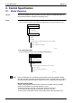
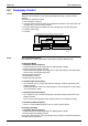
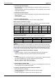
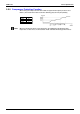
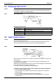
Table Of Contents
- Cover
- Table of Contents
- Part 1 List of Functions
- Part 2 Specifications
- Part 3 Printed Circuit Board Connector Wiring Diagram
- Part 4 Function and Control
- Part 5 Operation Manual
- Part 6 Service Diagnosis
- 1. Caution for Diagnosis
- 2. Problem Symptoms and Measures
- 3. Service Check Function
- 4. Code Indication on the Remote Controller
- 5. Troubleshooting
- 5.1 Indoor Units
- 5.2 Outdoor Units
- 5.3 Indoor Unit PCB Abnormality A1
- 5.4 Freeze-up Protection Control or High Pressure Control A5
- 5.5 Fan Motor or Related Abnormality A6
- 5.6 Thermistor or Related Abnormality (Indoor Unit) C4,C9
- 5.7 Front Panel Open / Close Fault C7
- 5.8 Signal Transmission Error (between Indoor and OutdoorUnit) U4
- 5.9 Unspecified Voltage (between Indoor and Outdoor Units) UA
- 5.10 Freeze-up Protection Control A5
- 5.11 Outdoor Unit PCB Abnormality E1
- 5.12 OL Activation (Compressor Overload) E5
- 5.13 Compressor Lock E6
- 5.14 DC Fan Lock E7
- 5.15 Input Over Current Detection E8
- 5.16 Discharge Pipe Temperature Control F3
- 5.17 High Pressure Control in Cooling F6
- 5.18 Compressor Sensor System Abnormality H0
- 5.19 Position Sensor Abnormality H6
- 5.20 CT or Related Abnormality H8
- 5.21 Thermistor or Related Abnormality (Outdoor Unit) P4,J3,J6,J8,J9,H9
- 5.22 Electrical Box Temperature Rise L3
- 5.23 Radiation Fin Temperature Rise L4
- 5.24 Output Over Current Detection L5
- 5.25 Insufficient Gas U0
- 5.26 Low-voltage Detection or Over-voltage Detection U2
- 5.27 Signal Transmission Error (on Outdoor Unit PCB) U7
- 5.28 Anti-icing Function in Other Rooms / UnspecifiedVoltage (between Indoor and Outdoor Units) UA,UH
- 6. Check
- Part 7 Removal Procedure
- Part 8 Others
- Part 9 Appendix
- Index
- Drawings & Flow Charts

Control Specification SiBE12-713
86 Function and Control
3.3 Controls at Mode Changing / Start-up
3.3.1 Preheating Operation
Outline Operate the inverter in the open phase operation with the conditions including the preheating
command from the indoor, the outdoor air temperature and discharge pipe temperature.
The power consumption of preheating operation is 35W. (The total power consumption depends
on the number of the indoor units.)
Detail Preheating ON Condition
When outdoor air temperature is below 10.5°C or discharge pipe temperature is below
10.5°C, inverter in open phase operation starts.
OFF Condition
When outdoor air temperature is higher than 12°C or discharge pipe temperature is higher
than 12°C, inverter in open phase operation stops.
3.3.2 Four Way Valve Switching
Outline of heating
operation
Heat Pump Only
During the heating operation current must be conducted and during cooling and defrosting
current must not be conducted. In order to eliminate the switching sound (as the four way valve
coil switches from ON to OFF) when the heating is stopped, the delay switch of the four way
valve must be carried out after the operation stopped.
Detail The OFF delay of four way valve
Energize the coil for 150 sec after unit operation is stopped.
3.3.3 Four Way Valve Operation Compensation
Outline Heat Pump Only
At the beginning of the operation as the four way valve is switched, acquire the differential
pressure required for activating the four way valve by having output the operating frequency,
which is more than a certain fixed frequency, for a certain fixed time.
The lower limit frequency is restricted to 40Hz for 70 seconds on both cooling and heating,
except under the condition of heating overload (outdoor temperature
≥
15 degree).
Detail Staring Conditions
1. When starting compressor for heating.
2. When the operating mode changes from the previous time.
3. When starting compressor for rushing defrosting or resetting.
4. When starting compressor for the first time after the reset with the power is ON.
Set the lower limit frequency to 40 (model by model) Hz for 70 seconds with any conditions
1 through 4 above.
3.3.4 3 Minutes Stand-by
Prohibit to turn ON the compressor for 3 minutes after turning it off.
(Except when defrosting. (Only for Heat Pump Model).)