
Specifications
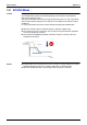
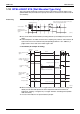
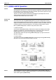
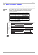
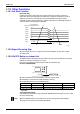
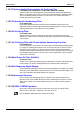
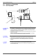
Table Of Contents
- Cover
- Table of Contents
- Part 1 List of Functions
- Part 2 Specifications
- Part 3 Printed Circuit Board Connector Wiring Diagram
- Part 4 Function and Control
- Part 5 Operation Manual
- Part 6 Service Diagnosis
- 1. Caution for Diagnosis
- 2. Problem Symptoms and Measures
- 3. Service Check Function
- 4. Code Indication on the Remote Controller
- 5. Troubleshooting
- 5.1 Indoor Units
- 5.2 Outdoor Units
- 5.3 Indoor Unit PCB Abnormality A1
- 5.4 Freeze-up Protection Control or High Pressure Control A5
- 5.5 Fan Motor or Related Abnormality A6
- 5.6 Thermistor or Related Abnormality (Indoor Unit) C4,C9
- 5.7 Front Panel Open / Close Fault C7
- 5.8 Signal Transmission Error (between Indoor and OutdoorUnit) U4
- 5.9 Unspecified Voltage (between Indoor and Outdoor Units) UA
- 5.10 Freeze-up Protection Control A5
- 5.11 Outdoor Unit PCB Abnormality E1
- 5.12 OL Activation (Compressor Overload) E5
- 5.13 Compressor Lock E6
- 5.14 DC Fan Lock E7
- 5.15 Input Over Current Detection E8
- 5.16 Discharge Pipe Temperature Control F3
- 5.17 High Pressure Control in Cooling F6
- 5.18 Compressor Sensor System Abnormality H0
- 5.19 Position Sensor Abnormality H6
- 5.20 CT or Related Abnormality H8
- 5.21 Thermistor or Related Abnormality (Outdoor Unit) P4,J3,J6,J8,J9,H9
- 5.22 Electrical Box Temperature Rise L3
- 5.23 Radiation Fin Temperature Rise L4
- 5.24 Output Over Current Detection L5
- 5.25 Insufficient Gas U0
- 5.26 Low-voltage Detection or Over-voltage Detection U2
- 5.27 Signal Transmission Error (on Outdoor Unit PCB) U7
- 5.28 Anti-icing Function in Other Rooms / UnspecifiedVoltage (between Indoor and Outdoor Units) UA,UH
- 6. Check
- Part 7 Removal Procedure
- Part 8 Others
- Part 9 Appendix
- Index
- Drawings & Flow Charts

Main Functions SiBE12-713
76 Function and Control
1.13.4 Titanium Apatite Photocatalytic Air-Purifying Filter
For FTK(X)S20-50D, FTK(X)S50-71F, FVXS25-50F, FTXG25/35E, CTXG50E
This filter combines the Air Purifying Filter and Titanium Apatite Photocatalytic Deodorizing
Filter in a single highly effective unit. The filter traps microscopic particles, decompose odours
and even deactivates bacteria and viruses. It lasts for three years without replacement if
washed about once every six months.
1.13.5 Photocatalytic Deodorizing Filter
For FLK(X)S25-60B
Photocatalytic Deodorizing Filter demonstrates powerful oxidation characteristics when
subjected to harmless ultraviolet light. Photocatalytic deodorizing power is recovered simply by
exposing the filter to the sun for 6 hours once every 6 months.
1.13.6 Air-Purifying Filter
For FLK(X)S25-60B
A double structure made up of a bacteriostatic filter and an Air-Purifying Filter traps dust,
mildew, mites, tobacco smoke, and allergy-causing pollen. Replace the Air-Purifying Filter once
every 3 months.
1.13.7 Air Purifying Filter with Photocatalytic Deodorizing Function
For FTK(X)S20-35C
This filter incorporates the benefits the Air Purifying Filter and Photocatalytic Deodorizing Filter
in a single unit. Combining the two filters in this way increases the active surface area of the
new filter. This larger surface area allows the filter to effectively trap microscopic particles,
decompose odours and deactivate bacteria and viruses even for the high volume of air required
to air-condition large living rooms. The filter can be used for approximately 3 years if periodic
maintenance is performed.
1.13.8 Mold Proof Air Filter (Prefilter)
For all indoor units
The filter net is treated with mold resisting agent TBZ (harmless, colorless, and odorless). Due
to this treatment, the amount of mold growth is much smaller than that of normal filters.
1.13.9 Self-Diagnosis Digital Display
The microcomputer continuously monitors main operating conditions of the indoor unit, outdoor
unit and the entire system. When an abnormality occur, the LCD remote controller displays error
code. These indications allow prompt maintenance operations.
1.13.10Auto-restart Function
Even if a power failure (including one for just a moment) occurs during the operation, the
operation restarts in the condition before power failure automatically when power is restored.
(Note) It takes 3 minutes to restart the operation because the 3 minute stand-by function is
activated.
1.13.11WEEKLY TIMER Operation
Up to 4 timer settings can be saved for each day of the week (up to 28 settings in total).
Those 3 items of “ON / OFF”, “temperature” and “time” can be set.
Refer to “WEEKLY TIMER Operation” on page 198 for detail.