
Specifications
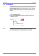
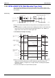
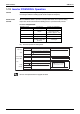
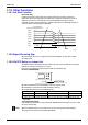
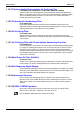
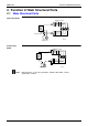
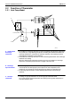
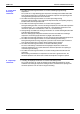
Table Of Contents
- Cover
- Table of Contents
- Part 1 List of Functions
- Part 2 Specifications
- Part 3 Printed Circuit Board Connector Wiring Diagram
- Part 4 Function and Control
- Part 5 Operation Manual
- Part 6 Service Diagnosis
- 1. Caution for Diagnosis
- 2. Problem Symptoms and Measures
- 3. Service Check Function
- 4. Code Indication on the Remote Controller
- 5. Troubleshooting
- 5.1 Indoor Units
- 5.2 Outdoor Units
- 5.3 Indoor Unit PCB Abnormality A1
- 5.4 Freeze-up Protection Control or High Pressure Control A5
- 5.5 Fan Motor or Related Abnormality A6
- 5.6 Thermistor or Related Abnormality (Indoor Unit) C4,C9
- 5.7 Front Panel Open / Close Fault C7
- 5.8 Signal Transmission Error (between Indoor and OutdoorUnit) U4
- 5.9 Unspecified Voltage (between Indoor and Outdoor Units) UA
- 5.10 Freeze-up Protection Control A5
- 5.11 Outdoor Unit PCB Abnormality E1
- 5.12 OL Activation (Compressor Overload) E5
- 5.13 Compressor Lock E6
- 5.14 DC Fan Lock E7
- 5.15 Input Over Current Detection E8
- 5.16 Discharge Pipe Temperature Control F3
- 5.17 High Pressure Control in Cooling F6
- 5.18 Compressor Sensor System Abnormality H0
- 5.19 Position Sensor Abnormality H6
- 5.20 CT or Related Abnormality H8
- 5.21 Thermistor or Related Abnormality (Outdoor Unit) P4,J3,J6,J8,J9,H9
- 5.22 Electrical Box Temperature Rise L3
- 5.23 Radiation Fin Temperature Rise L4
- 5.24 Output Over Current Detection L5
- 5.25 Insufficient Gas U0
- 5.26 Low-voltage Detection or Over-voltage Detection U2
- 5.27 Signal Transmission Error (on Outdoor Unit PCB) U7
- 5.28 Anti-icing Function in Other Rooms / UnspecifiedVoltage (between Indoor and Outdoor Units) UA,UH
- 6. Check
- Part 7 Removal Procedure
- Part 8 Others
- Part 9 Appendix
- Index
- Drawings & Flow Charts
SiBE12-713 Main Functions
Function and Control 73
1.11 HOME LEAVE Operation
Outline In order to respond to the customer's need for immediate heating and cooling of the room after
returning home or for house care, a measure to switch the temperature and air volume from that
for normal time over to outing time by one touch is provided. (This function responds also to the
need for keeping up with weak cooling or heating.)
This time, we seek for simplicity of operation by providing the special temperature and air
volume control for outing to be set by the exclusive button.
The SkyAir indoor models also have the function.
Detail of the
Control
1. Start of Function
The function starts when the [HOME LEAVE] button is pressed in cooling mode or heating
mode (including stopping and powerful operation). If this button is pressed while the operation is
stopped, the function becomes effective when the operation is started. If this button is pressed
in powerful operation, the powerful operation is reset and this function becomes effective.
The [HOME LEAVE] button is ineffective in dry mode and fan mode.
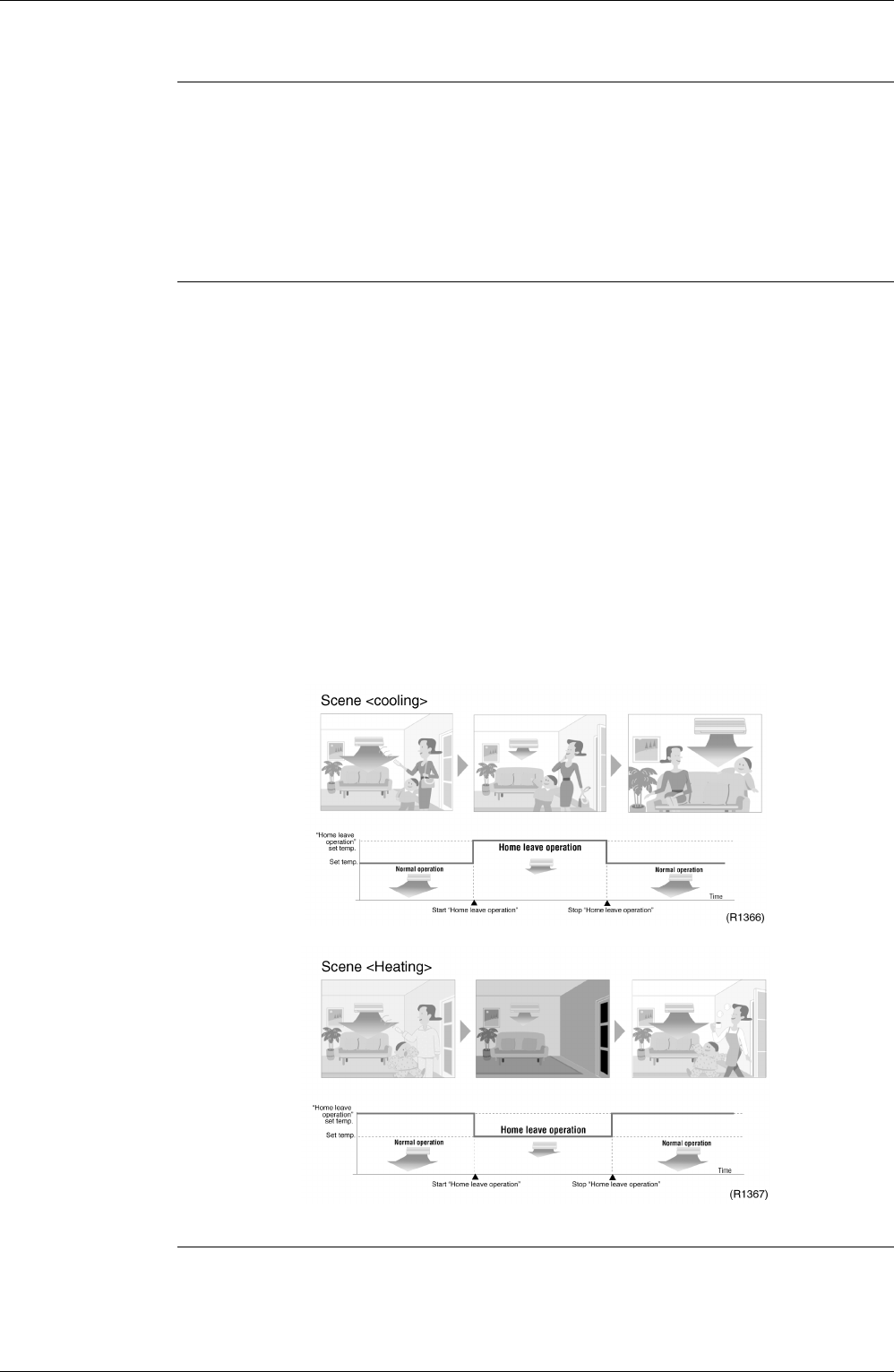
2. Details of Function
A mark representing [HOME LEAVE] is indicated on the liquid crystal display of the remote
controller. The indoor unit is operated according to the set temperature and air volume for
HOME LEAVE which were pre-set in the memory of the remote controller.
The LED (Red) of indoor unit representing [HOME LEAVE] lights up. (It goes out when the
operation is stopped.)
3. End of Function
The function ends when the [HOME LEAVE] button is pressed again during [HOME LEAVE]
operation or when the powerful operation button is pressed.
Others The set temperature and set air volume are memorized in the remote controller. When the
remote controller is reset due to replacement of battery, it is necessary to set the temperature
and air volume again for [HOME LEAVE].