
Specifications
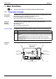
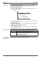
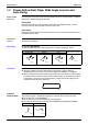
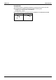
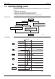
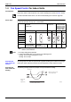
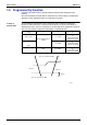
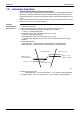
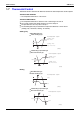
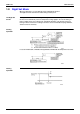
Table Of Contents
- Cover
- Table of Contents
- Part 1 List of Functions
- Part 2 Specifications
- Part 3 Printed Circuit Board Connector Wiring Diagram
- Part 4 Function and Control
- Part 5 Operation Manual
- Part 6 Service Diagnosis
- 1. Caution for Diagnosis
- 2. Problem Symptoms and Measures
- 3. Service Check Function
- 4. Code Indication on the Remote Controller
- 5. Troubleshooting
- 5.1 Indoor Units
- 5.2 Outdoor Units
- 5.3 Indoor Unit PCB Abnormality A1
- 5.4 Freeze-up Protection Control or High Pressure Control A5
- 5.5 Fan Motor or Related Abnormality A6
- 5.6 Thermistor or Related Abnormality (Indoor Unit) C4,C9
- 5.7 Front Panel Open / Close Fault C7
- 5.8 Signal Transmission Error (between Indoor and OutdoorUnit) U4
- 5.9 Unspecified Voltage (between Indoor and Outdoor Units) UA
- 5.10 Freeze-up Protection Control A5
- 5.11 Outdoor Unit PCB Abnormality E1
- 5.12 OL Activation (Compressor Overload) E5
- 5.13 Compressor Lock E6
- 5.14 DC Fan Lock E7
- 5.15 Input Over Current Detection E8
- 5.16 Discharge Pipe Temperature Control F3
- 5.17 High Pressure Control in Cooling F6
- 5.18 Compressor Sensor System Abnormality H0
- 5.19 Position Sensor Abnormality H6
- 5.20 CT or Related Abnormality H8
- 5.21 Thermistor or Related Abnormality (Outdoor Unit) P4,J3,J6,J8,J9,H9
- 5.22 Electrical Box Temperature Rise L3
- 5.23 Radiation Fin Temperature Rise L4
- 5.24 Output Over Current Detection L5
- 5.25 Insufficient Gas U0
- 5.26 Low-voltage Detection or Over-voltage Detection U2
- 5.27 Signal Transmission Error (on Outdoor Unit PCB) U7
- 5.28 Anti-icing Function in Other Rooms / UnspecifiedVoltage (between Indoor and Outdoor Units) UA,UH
- 6. Check
- Part 7 Removal Procedure
- Part 8 Others
- Part 9 Appendix
- Index
- Drawings & Flow Charts
Main Functions SiBE12-713
68 Function and Control
1.7 Thermostat Control
Thermostat control is based on the difference between the room temperature and the setpoint.
Thermostat OFF Condition
The temperature difference is in the zone A.
Thermostat ON Condition
The temperature difference is above the zone C after being in the zone A.
The system resumes from defrost control in any zones except A.
The operation turns on in any zones except A.
The monitoring time has passed while the temperature difference is in the zone B.
(Cooling / Dry : 10 minutes, Heating : 10 seconds)
Cooling / Dry
Wall Mounted Type
Floor standing Type
Floor/Ceiling suspended Type
Duct Connected Type
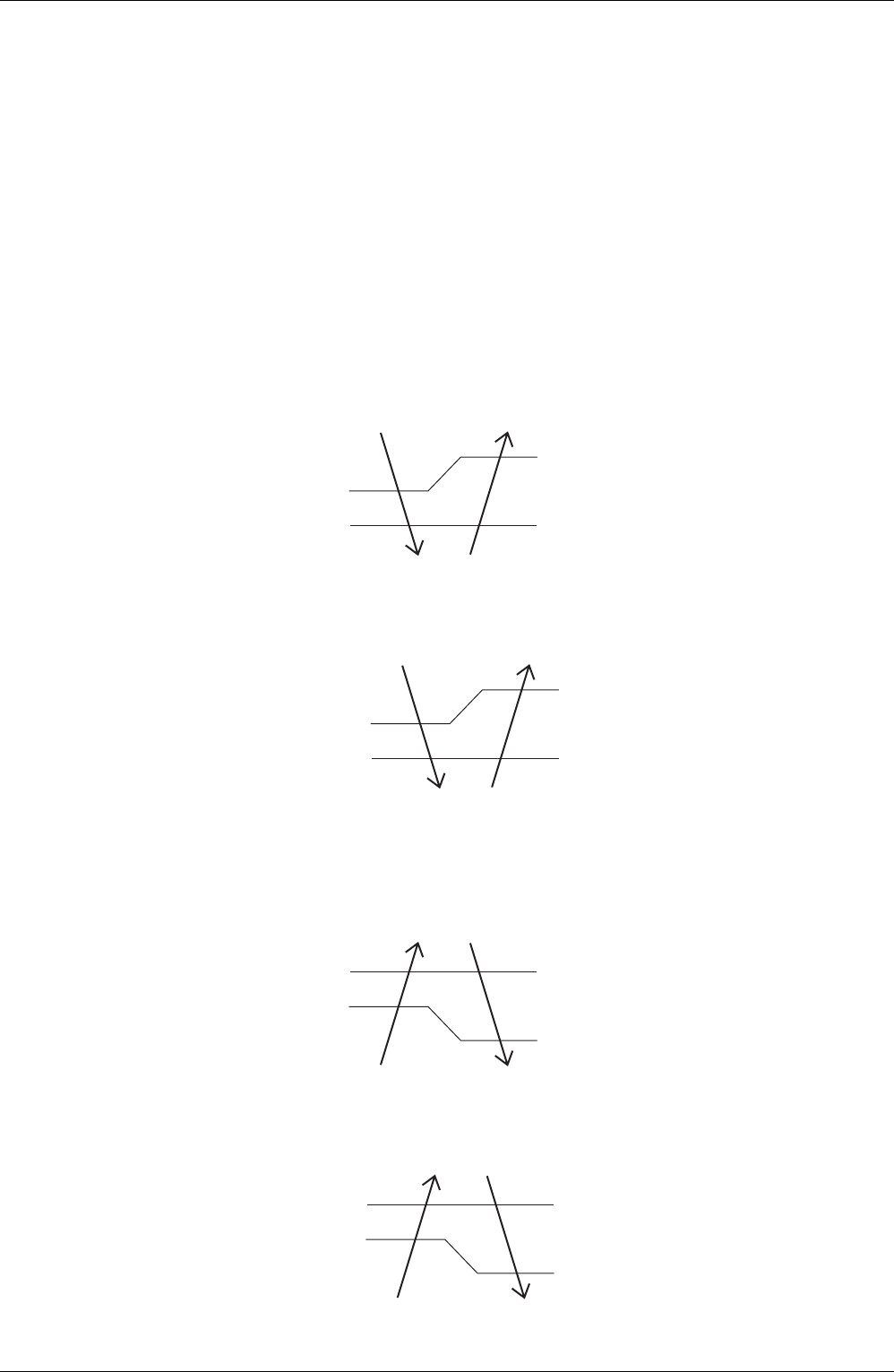
Heating
Wall Mounted Type
Floor standing Type
Floor/Ceiling suspended Type
Duct Connected Type
B
A
OFF
ON
C
Cooling : – 0.5˚C
Dry : – 0.5˚C
Room temperature - setpoint
Cooling : – 2.0˚C
Dry : – 2.5~– 2.0˚C
(R4668)
B
A
OFF
ON
C
– 1.5˚C
Room temperature - setpoint
Cooling : – 2.0˚C
Dry : – 2.5~– 2.0˚C
Cooling : – 1.0˚C
Dry : – 1.0˚C
(R6032)
B
A
OFF
ON
C
1.5˚C
Room temperature - setpoint
0˚C
(R4669)
B
A
OFF
ON
C
1.5˚C
1.0˚C
Room temperature - setpoint
0.5˚C
(R6033)