
Specifications
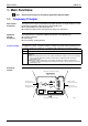
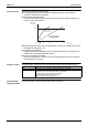
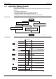
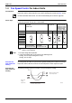
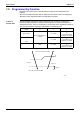
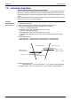
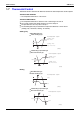
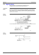
Table Of Contents
- Cover
- Table of Contents
- Part 1 List of Functions
- Part 2 Specifications
- Part 3 Printed Circuit Board Connector Wiring Diagram
- Part 4 Function and Control
- Part 5 Operation Manual
- Part 6 Service Diagnosis
- 1. Caution for Diagnosis
- 2. Problem Symptoms and Measures
- 3. Service Check Function
- 4. Code Indication on the Remote Controller
- 5. Troubleshooting
- 5.1 Indoor Units
- 5.2 Outdoor Units
- 5.3 Indoor Unit PCB Abnormality A1
- 5.4 Freeze-up Protection Control or High Pressure Control A5
- 5.5 Fan Motor or Related Abnormality A6
- 5.6 Thermistor or Related Abnormality (Indoor Unit) C4,C9
- 5.7 Front Panel Open / Close Fault C7
- 5.8 Signal Transmission Error (between Indoor and OutdoorUnit) U4
- 5.9 Unspecified Voltage (between Indoor and Outdoor Units) UA
- 5.10 Freeze-up Protection Control A5
- 5.11 Outdoor Unit PCB Abnormality E1
- 5.12 OL Activation (Compressor Overload) E5
- 5.13 Compressor Lock E6
- 5.14 DC Fan Lock E7
- 5.15 Input Over Current Detection E8
- 5.16 Discharge Pipe Temperature Control F3
- 5.17 High Pressure Control in Cooling F6
- 5.18 Compressor Sensor System Abnormality H0
- 5.19 Position Sensor Abnormality H6
- 5.20 CT or Related Abnormality H8
- 5.21 Thermistor or Related Abnormality (Outdoor Unit) P4,J3,J6,J8,J9,H9
- 5.22 Electrical Box Temperature Rise L3
- 5.23 Radiation Fin Temperature Rise L4
- 5.24 Output Over Current Detection L5
- 5.25 Insufficient Gas U0
- 5.26 Low-voltage Detection or Over-voltage Detection U2
- 5.27 Signal Transmission Error (on Outdoor Unit PCB) U7
- 5.28 Anti-icing Function in Other Rooms / UnspecifiedVoltage (between Indoor and Outdoor Units) UA,UH
- 6. Check
- Part 7 Removal Procedure
- Part 8 Others
- Part 9 Appendix
- Index
- Drawings & Flow Charts
Main Functions SiBE12-713
66 Function and Control
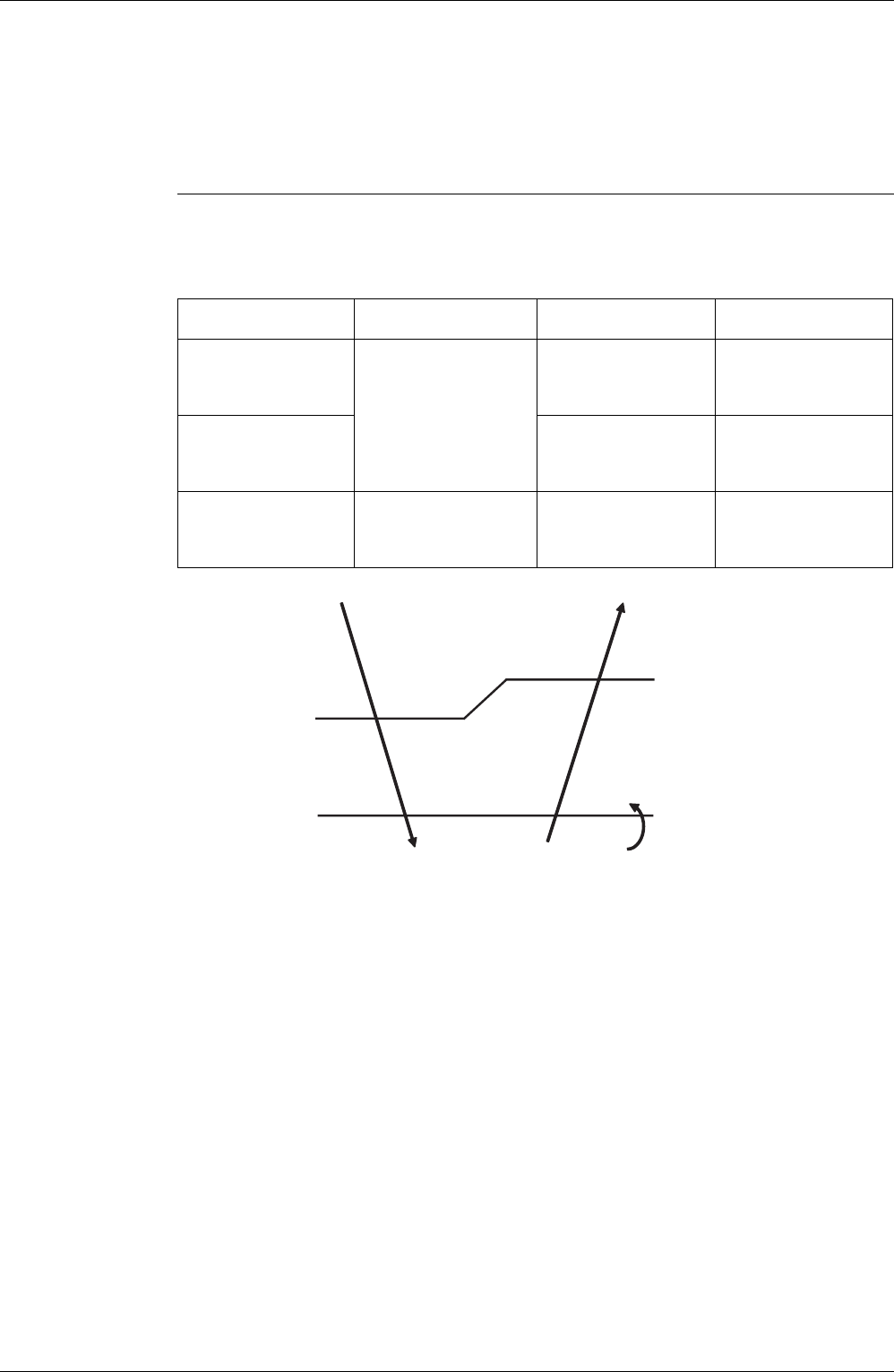
1.5 Programme Dry Function
Programme dry function removes humidity while preventing the room temperature from
lowering.
Since the microcomputer controls both the temperature and air flow volume, the temperature
adjustment and fan adjustment buttons are inoperable in this mode.
In Case of
Inverter Units
The microcomputer automatically sets the temperature and fan settings. The difference
between the room temperature at startup and the temperature set by the microcomputer is
divided into two zones. Then, the unit operates in the dry mode with an appropriate capacity for
each zone to maintain the temperature and humidity at a comfortable level.
Room temperature at
startup
Set temperature
X
Thermostat OFF point
Y
Thermostat ON point
Z
24ºC or more
Room temperature at
startup
X
–
2.5ºC
X
–
0.5ºC
or
Y + 0.5ºC (zone B)
continues for 10 min.
23.5ºC
X
–
2.0ºC
X
–
0.5ºC
or
Y + 0.5ºC (zone B)
continues for 10 min.
~
18ºC
18ºC X
–
2.0ºC
X
–
0.5ºC = 17.5ºC
or
Y + 0.5ºC (zone B)
continues for 10 min.
17.5ºC
~
Z
Y
Zone B
Zone B
Zone A = Thermostat OFF
Zone C = Thermostat ON
+0.5ºC
(R6841)