
Specifications
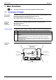
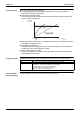
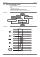
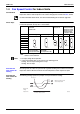
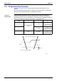
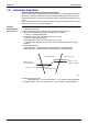
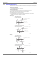
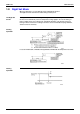
Table Of Contents
- Cover
- Table of Contents
- Part 1 List of Functions
- Part 2 Specifications
- Part 3 Printed Circuit Board Connector Wiring Diagram
- Part 4 Function and Control
- Part 5 Operation Manual
- Part 6 Service Diagnosis
- 1. Caution for Diagnosis
- 2. Problem Symptoms and Measures
- 3. Service Check Function
- 4. Code Indication on the Remote Controller
- 5. Troubleshooting
- 5.1 Indoor Units
- 5.2 Outdoor Units
- 5.3 Indoor Unit PCB Abnormality A1
- 5.4 Freeze-up Protection Control or High Pressure Control A5
- 5.5 Fan Motor or Related Abnormality A6
- 5.6 Thermistor or Related Abnormality (Indoor Unit) C4,C9
- 5.7 Front Panel Open / Close Fault C7
- 5.8 Signal Transmission Error (between Indoor and OutdoorUnit) U4
- 5.9 Unspecified Voltage (between Indoor and Outdoor Units) UA
- 5.10 Freeze-up Protection Control A5
- 5.11 Outdoor Unit PCB Abnormality E1
- 5.12 OL Activation (Compressor Overload) E5
- 5.13 Compressor Lock E6
- 5.14 DC Fan Lock E7
- 5.15 Input Over Current Detection E8
- 5.16 Discharge Pipe Temperature Control F3
- 5.17 High Pressure Control in Cooling F6
- 5.18 Compressor Sensor System Abnormality H0
- 5.19 Position Sensor Abnormality H6
- 5.20 CT or Related Abnormality H8
- 5.21 Thermistor or Related Abnormality (Outdoor Unit) P4,J3,J6,J8,J9,H9
- 5.22 Electrical Box Temperature Rise L3
- 5.23 Radiation Fin Temperature Rise L4
- 5.24 Output Over Current Detection L5
- 5.25 Insufficient Gas U0
- 5.26 Low-voltage Detection or Over-voltage Detection U2
- 5.27 Signal Transmission Error (on Outdoor Unit PCB) U7
- 5.28 Anti-icing Function in Other Rooms / UnspecifiedVoltage (between Indoor and Outdoor Units) UA,UH
- 6. Check
- Part 7 Removal Procedure
- Part 8 Others
- Part 9 Appendix
- Index
- Drawings & Flow Charts
SiBE12-713 Main Functions
Function and Control 65
1.4 Fan Speed Control for Indoor Units
Control Mode The airflow rate can be automatically controlled depending on the difference between the set
temperature and the room temperature. This is done through phase control and Hall IC control.
For more information about Hall IC, refer to the troubleshooting for fan motor on page 239.
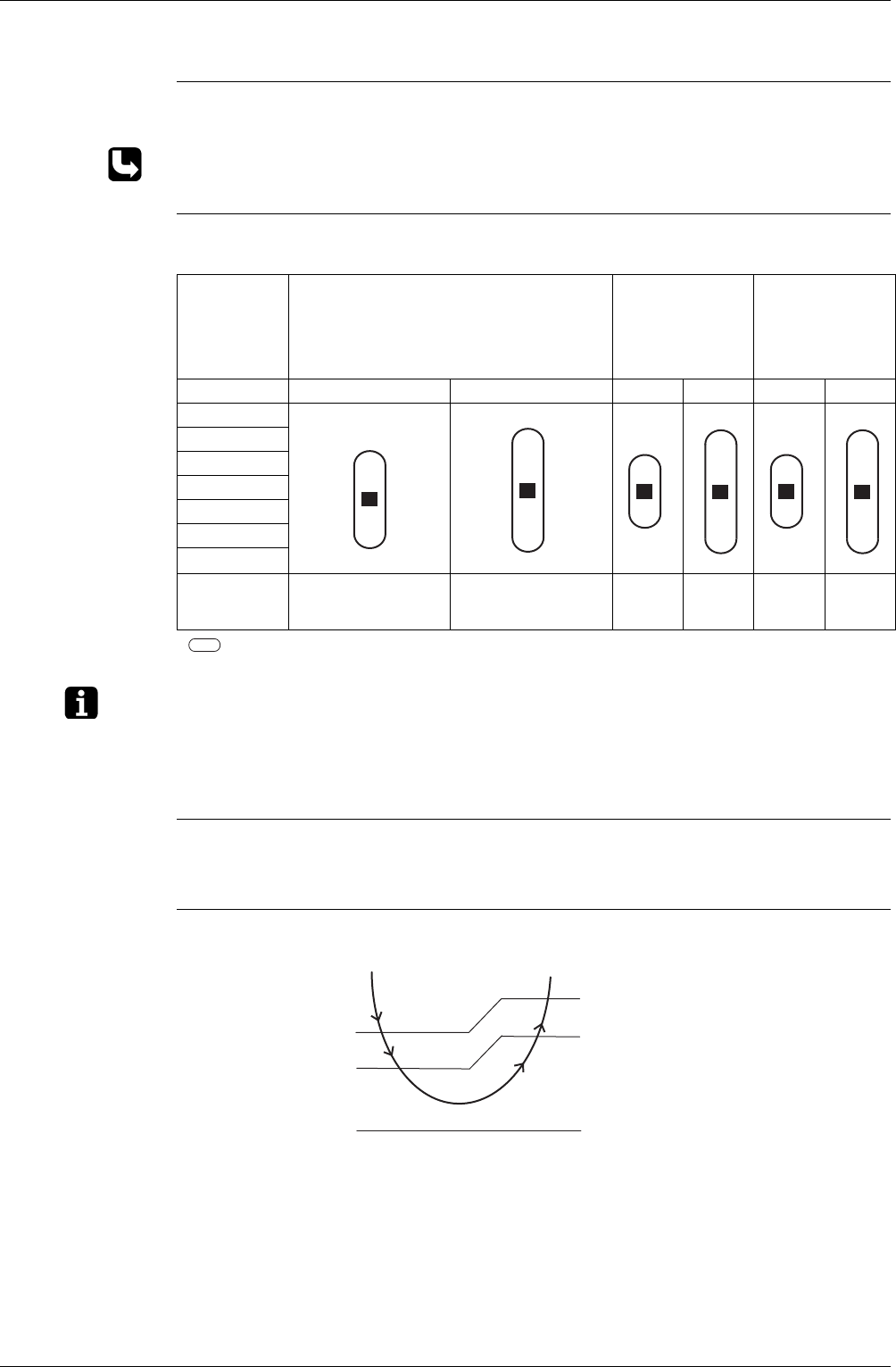
Phase Steps Phase control and fan speed control contains 9 steps: LLL, LL, SL, L, ML, M, MH, H and HH.
In automatic operation, the step “SL” is not available.
= Within this range the airflow rate is automatically controlled when the FAN setting
button is set to automatic.
Note: 1. Fan stops during defrost operation.
2. In time of thermostat OFF, the fan rotates at the following speed.
Cooling : The fan keeps rotating at the set tap.
Heating : The fan stops.
Automatic Air
Flow Control for
Heating
On heating mode, the indoor fan speed will be regulated according to the indoor heat exchanger
temperature and the difference between the room temperature and the required set point.
Automatic Air
Flow Control for
Cooling
The following drawing explains the principle of fan speed control for cooling:
FTXG25/35E
CTXG50E
FVXS25-50F
FTK(X)S50-71E
FTK(X)S71B
FTK(X)S20-50D
FTK(X)S20-35CA
FDK(X)S25-35EA
FDK(X)S25-35CA
FDK(X)S50-60C
FLK(X)S25-60BA
Step Cooling Heating Cooling Heating Cooling Heating
LLL
LL
L
ML
M
MH
H
HH (Powerful) H+70 (FTXG25/35E)
H+50 (CTXG50E)
H+40 (FVXS25-50F)
H+50 (FTXG25/35E,
CTXG50E)
H+40 (FVXS25-50F)
H+90 H+90 H+50 H+50
(R6035)
(R6036)
(R6037)
(R6036)
(R6037)
(R6036)
+1.5˚C
+0.5˚C
+2˚C
+1˚C
M
ML
L
fan speed
Difference between room
and set temperature
Thermostat
setting
temperature
(R4594)
DC motor: Rotation speed control
AC motor: Phase control