
Specifications
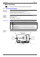
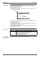
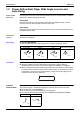
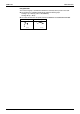
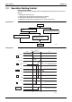
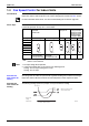
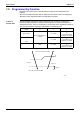
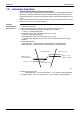
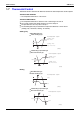
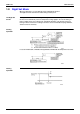
Table Of Contents
- Cover
- Table of Contents
- Part 1 List of Functions
- Part 2 Specifications
- Part 3 Printed Circuit Board Connector Wiring Diagram
- Part 4 Function and Control
- Part 5 Operation Manual
- Part 6 Service Diagnosis
- 1. Caution for Diagnosis
- 2. Problem Symptoms and Measures
- 3. Service Check Function
- 4. Code Indication on the Remote Controller
- 5. Troubleshooting
- 5.1 Indoor Units
- 5.2 Outdoor Units
- 5.3 Indoor Unit PCB Abnormality A1
- 5.4 Freeze-up Protection Control or High Pressure Control A5
- 5.5 Fan Motor or Related Abnormality A6
- 5.6 Thermistor or Related Abnormality (Indoor Unit) C4,C9
- 5.7 Front Panel Open / Close Fault C7
- 5.8 Signal Transmission Error (between Indoor and OutdoorUnit) U4
- 5.9 Unspecified Voltage (between Indoor and Outdoor Units) UA
- 5.10 Freeze-up Protection Control A5
- 5.11 Outdoor Unit PCB Abnormality E1
- 5.12 OL Activation (Compressor Overload) E5
- 5.13 Compressor Lock E6
- 5.14 DC Fan Lock E7
- 5.15 Input Over Current Detection E8
- 5.16 Discharge Pipe Temperature Control F3
- 5.17 High Pressure Control in Cooling F6
- 5.18 Compressor Sensor System Abnormality H0
- 5.19 Position Sensor Abnormality H6
- 5.20 CT or Related Abnormality H8
- 5.21 Thermistor or Related Abnormality (Outdoor Unit) P4,J3,J6,J8,J9,H9
- 5.22 Electrical Box Temperature Rise L3
- 5.23 Radiation Fin Temperature Rise L4
- 5.24 Output Over Current Detection L5
- 5.25 Insufficient Gas U0
- 5.26 Low-voltage Detection or Over-voltage Detection U2
- 5.27 Signal Transmission Error (on Outdoor Unit PCB) U7
- 5.28 Anti-icing Function in Other Rooms / UnspecifiedVoltage (between Indoor and Outdoor Units) UA,UH
- 6. Check
- Part 7 Removal Procedure
- Part 8 Others
- Part 9 Appendix
- Index
- Drawings & Flow Charts
Main Functions SiBE12-713
62 Function and Control
1.2 Power-Airflow Dual Flaps, Wide Angle Louvers and
Auto-Swing
Power-airflow
Dual Flaps
The large flaps send a large volume of air downwards to the floor. The flap provides an optimum
control area in cooling, heating and dry mode.
Heating Mode
During heating mode, the large flap enables direct warm air straight downwards. The flap
presses the warm air above the floor to reach the entire room.
Cooling Mode
During cooling mode, the flap retracts into the indoor unit. Then, cool air can be blown far and
pervaded all over the room.
Wide-Angle
Louvers
The louvres, made of elastic synthetic resin, provide a wide range of airflow that guarantees a
comfortable air distribution.
Auto-Swing In case of FTK(X)S20-50D
The following table explains the auto swing process for heating, cooling, dry and fan :
3-D Airflow FTXG25-35E, CTXG50E, FTK(X)S50-71F
Alternative repetition of vertical and horizontal swing motions enables uniform air-
conditioning of the entire room. This function is effective for starting the air conditioner.
When the horizontal swing and vertical swing are both set to auto mode, the airflow become
3-D airflow and the horizontal swing and vertical swing motions are alternated. The order of
swing motion is such that it turns counterclockwise, starting from the right upper point as
viewed to the front side of the indoor unit.
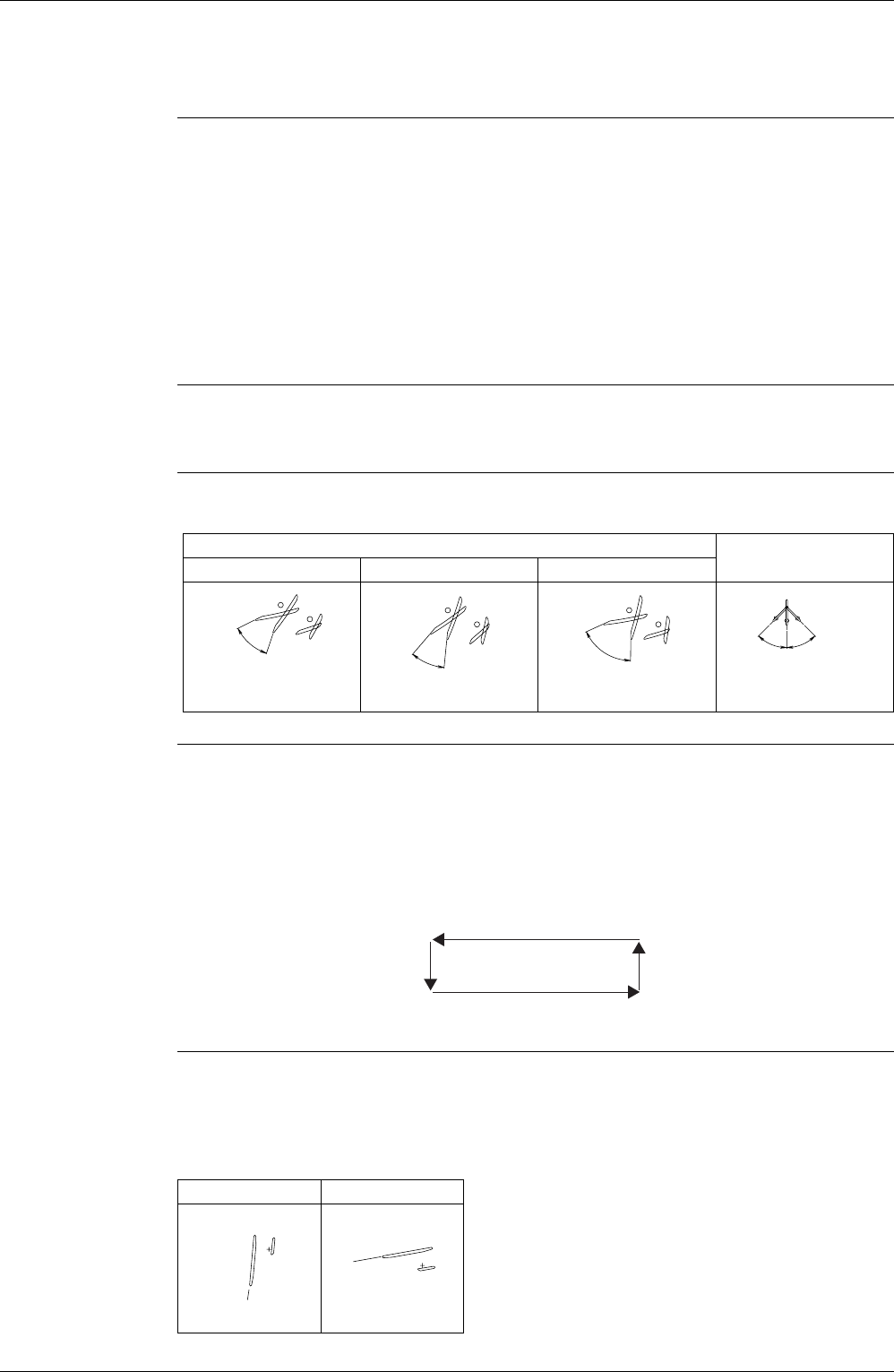
COMFORT
AIRFLOW Mode
FTXG25-35E, CTXG50E
The vertical swing flap is controlled not to blow the air directly on the person in the room.
The airflow rate is set to AUTOMATIC.
The airflow rate has the upper limit (M tap) in heating mode.
The latest command has the priority between POWERFUL and COMFORT AIRFLOW.
Vertical Swing (up and down)
Horizontal Swing
(right and left: manual)
Cooling / Dry Heating Fan
(R4281)
10
°
50
°
(R4282)
30
°
65
°
(R4283)
5
°
70
°
(R4284)
45
°
45
°
(R1024)
Heating Cooling, Dry
(R3297)
80˚
(R3298)
5˚