
Specifications
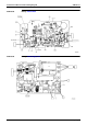
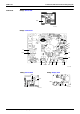
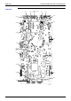
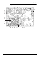
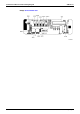
Table Of Contents
- Cover
- Table of Contents
- Part 1 List of Functions
- Part 2 Specifications
- Part 3 Printed Circuit Board Connector Wiring Diagram
- Part 4 Function and Control
- Part 5 Operation Manual
- Part 6 Service Diagnosis
- 1. Caution for Diagnosis
- 2. Problem Symptoms and Measures
- 3. Service Check Function
- 4. Code Indication on the Remote Controller
- 5. Troubleshooting
- 5.1 Indoor Units
- 5.2 Outdoor Units
- 5.3 Indoor Unit PCB Abnormality A1
- 5.4 Freeze-up Protection Control or High Pressure Control A5
- 5.5 Fan Motor or Related Abnormality A6
- 5.6 Thermistor or Related Abnormality (Indoor Unit) C4,C9
- 5.7 Front Panel Open / Close Fault C7
- 5.8 Signal Transmission Error (between Indoor and OutdoorUnit) U4
- 5.9 Unspecified Voltage (between Indoor and Outdoor Units) UA
- 5.10 Freeze-up Protection Control A5
- 5.11 Outdoor Unit PCB Abnormality E1
- 5.12 OL Activation (Compressor Overload) E5
- 5.13 Compressor Lock E6
- 5.14 DC Fan Lock E7
- 5.15 Input Over Current Detection E8
- 5.16 Discharge Pipe Temperature Control F3
- 5.17 High Pressure Control in Cooling F6
- 5.18 Compressor Sensor System Abnormality H0
- 5.19 Position Sensor Abnormality H6
- 5.20 CT or Related Abnormality H8
- 5.21 Thermistor or Related Abnormality (Outdoor Unit) P4,J3,J6,J8,J9,H9
- 5.22 Electrical Box Temperature Rise L3
- 5.23 Radiation Fin Temperature Rise L4
- 5.24 Output Over Current Detection L5
- 5.25 Insufficient Gas U0
- 5.26 Low-voltage Detection or Over-voltage Detection U2
- 5.27 Signal Transmission Error (on Outdoor Unit PCB) U7
- 5.28 Anti-icing Function in Other Rooms / UnspecifiedVoltage (between Indoor and Outdoor Units) UA,UH
- 6. Check
- Part 7 Removal Procedure
- Part 8 Others
- Part 9 Appendix
- Index
- Drawings & Flow Charts
Printed Circuit Board Connector Wiring Diagram SiBE12-713
56 Printed Circuit Board Connector Wiring Diagram
1.6 Outdoor Units
Connectors PCB(1)(Main PCB)
PCB(2)(Service Monitor PCB)
Note: Other Designations
PCB(1)(Main PCB)
PCB(2)(Service Monitor PCB)
1) S10 Connector for terminal strip (indoor-outdoor transmission)
2) S15 Connector for COOL / HEAT mode lock
3) S20 Connector for electronic expansion valve coil A port (white)
4) S21 Connector for electronic expansion valve coil B port (red)
5) S22 Connector for electronic expansion valve coil C port (blue)
6) S23 Connector for electronic expansion valve coil D port (yellow)
7) S40 Connector for overload protector
8) S51, S101 Connector for service monitor PCB
9) S70 Connector for fan motor
10) S80 Connector for four way valve coil
11) S90 Connector for thermistors
(outdoor air, heat exchanger, and discharge pipe)
12) S92 Connector for gas pipe thermistor
13) S93 Connector for liquid pipe thermistor
14) AC1, AC2 Connector for terminal strip (power supply)
15) HR1, HR2 Connector for reactor
1) S52, S102 Connector for control PCB
1) FU1 Fuse (30A)
2) FU2, FU3 Fuse (3.15A)
3) V2, V3, V5
V9, V100
Varistor
1) LED A Service monitor LED (green)
2) LED1 - LED4 Service monitor LED (red)
3) SW1 Forced operation ON/OFF switch
4) SW2 Operation mode switch
5) SW3 Wiring error check switch
6) SW4 Priorily room setting switch
7) SW5 Night quiet mode setting switch