
Specifications
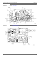
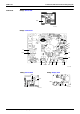
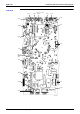
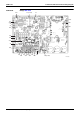
Table Of Contents
- Cover
- Table of Contents
- Part 1 List of Functions
- Part 2 Specifications
- Part 3 Printed Circuit Board Connector Wiring Diagram
- Part 4 Function and Control
- Part 5 Operation Manual
- Part 6 Service Diagnosis
- 1. Caution for Diagnosis
- 2. Problem Symptoms and Measures
- 3. Service Check Function
- 4. Code Indication on the Remote Controller
- 5. Troubleshooting
- 5.1 Indoor Units
- 5.2 Outdoor Units
- 5.3 Indoor Unit PCB Abnormality A1
- 5.4 Freeze-up Protection Control or High Pressure Control A5
- 5.5 Fan Motor or Related Abnormality A6
- 5.6 Thermistor or Related Abnormality (Indoor Unit) C4,C9
- 5.7 Front Panel Open / Close Fault C7
- 5.8 Signal Transmission Error (between Indoor and OutdoorUnit) U4
- 5.9 Unspecified Voltage (between Indoor and Outdoor Units) UA
- 5.10 Freeze-up Protection Control A5
- 5.11 Outdoor Unit PCB Abnormality E1
- 5.12 OL Activation (Compressor Overload) E5
- 5.13 Compressor Lock E6
- 5.14 DC Fan Lock E7
- 5.15 Input Over Current Detection E8
- 5.16 Discharge Pipe Temperature Control F3
- 5.17 High Pressure Control in Cooling F6
- 5.18 Compressor Sensor System Abnormality H0
- 5.19 Position Sensor Abnormality H6
- 5.20 CT or Related Abnormality H8
- 5.21 Thermistor or Related Abnormality (Outdoor Unit) P4,J3,J6,J8,J9,H9
- 5.22 Electrical Box Temperature Rise L3
- 5.23 Radiation Fin Temperature Rise L4
- 5.24 Output Over Current Detection L5
- 5.25 Insufficient Gas U0
- 5.26 Low-voltage Detection or Over-voltage Detection U2
- 5.27 Signal Transmission Error (on Outdoor Unit PCB) U7
- 5.28 Anti-icing Function in Other Rooms / UnspecifiedVoltage (between Indoor and Outdoor Units) UA,UH
- 6. Check
- Part 7 Removal Procedure
- Part 8 Others
- Part 9 Appendix
- Index
- Drawings & Flow Charts
Printed Circuit Board Connector Wiring Diagram SiBE12-713
54 Printed Circuit Board Connector Wiring Diagram
1.5 Ceiling Suspended Type
Connectors
1) X5A Connector for Terminal Strip (for Wired Remote Controller)
2) X14A Connector for Limit Switch (for Swing Flap)
3) X15A Connector for Drain Pump (Optional Accessory)
4) X17A Connector for Heat Exchanger Thermistor (2)
5) X18A Connector for Heat Exchanger Thermistor (1)
6) X19A Connector for Room Temperature Thermistor
7) X20A, X26A Connector for Fan Motor
8) X24A Connector for Wireless Remote Controller Receiver Unit
9) X25A Connector for Drain Pump Motor (Optional Accessory)
10) X27A Connector for Terminal Strip (for Inter Unit Wiring)
11) X29A Connector for Swing Motor
12) X33A Connector for Wring Adaptor PCB (Optional Accessory)
13) X35A Connector for Group Control Adaptor (Optional Accessory)
14) X40A Connector for ON/OFF Input from Outside (for Optional Accessory)
15) X60A, X61A Connector for Interface Adaptor (Optional Accessory)
Note: Other Designation
1) HAP Service Monitor LED