
Specifications
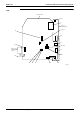
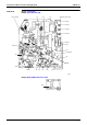
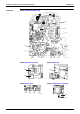
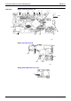
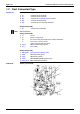
Table Of Contents
- Cover
- Table of Contents
- Part 1 List of Functions
- Part 2 Specifications
- Part 3 Printed Circuit Board Connector Wiring Diagram
- Part 4 Function and Control
- Part 5 Operation Manual
- Part 6 Service Diagnosis
- 1. Caution for Diagnosis
- 2. Problem Symptoms and Measures
- 3. Service Check Function
- 4. Code Indication on the Remote Controller
- 5. Troubleshooting
- 5.1 Indoor Units
- 5.2 Outdoor Units
- 5.3 Indoor Unit PCB Abnormality A1
- 5.4 Freeze-up Protection Control or High Pressure Control A5
- 5.5 Fan Motor or Related Abnormality A6
- 5.6 Thermistor or Related Abnormality (Indoor Unit) C4,C9
- 5.7 Front Panel Open / Close Fault C7
- 5.8 Signal Transmission Error (between Indoor and OutdoorUnit) U4
- 5.9 Unspecified Voltage (between Indoor and Outdoor Units) UA
- 5.10 Freeze-up Protection Control A5
- 5.11 Outdoor Unit PCB Abnormality E1
- 5.12 OL Activation (Compressor Overload) E5
- 5.13 Compressor Lock E6
- 5.14 DC Fan Lock E7
- 5.15 Input Over Current Detection E8
- 5.16 Discharge Pipe Temperature Control F3
- 5.17 High Pressure Control in Cooling F6
- 5.18 Compressor Sensor System Abnormality H0
- 5.19 Position Sensor Abnormality H6
- 5.20 CT or Related Abnormality H8
- 5.21 Thermistor or Related Abnormality (Outdoor Unit) P4,J3,J6,J8,J9,H9
- 5.22 Electrical Box Temperature Rise L3
- 5.23 Radiation Fin Temperature Rise L4
- 5.24 Output Over Current Detection L5
- 5.25 Insufficient Gas U0
- 5.26 Low-voltage Detection or Over-voltage Detection U2
- 5.27 Signal Transmission Error (on Outdoor Unit PCB) U7
- 5.28 Anti-icing Function in Other Rooms / UnspecifiedVoltage (between Indoor and Outdoor Units) UA,UH
- 6. Check
- Part 7 Removal Procedure
- Part 8 Others
- Part 9 Appendix
- Index
- Drawings & Flow Charts
SiBE12-713 Printed Circuit Board Connector Wiring Diagram
Printed Circuit Board Connector Wiring Diagram 49
1.3 Floor / Ceiling Suspended Dual Type
Connectors PCB(1) (Control PCB)
PCB(2) (Power Supply PCB)
PCB(3) (Display PCB)
PCB(4) (Signal Receiver PCB)
Note: Other designations
PCB(1) (Control PCB)
PCB(2) (Power Supply PCB)
PCB(3) (Display PCB)
PCB(4) (Signal Receiver PCB)
1) S6 Connector for swing motor (horizontal swing)
2) S7 Connector for AC fan motor
3) S21 Connector for centralized control
4) S24 Connector for display PCB
5) S26 Connector for signal receiver PCB
6) S32 Connector for heat exchanger thermistor
7) S37 Connector for power supply PCB
1) S36 Connector for control PCB
1) S25 Connector for control PCB
1) S27 Connector for control PCB
2) S31 Connector for room temperature thermistor
1) JA Address setting jumper
JB Fan speed setting when compressor is OFF on thermostat
JC Power failure recovery function
∗
Refer to page 321 for detail.
2) SW2 Select switch ceiling or floor
3) LED A LED for service monitor (green)
1) V1 Varistor
1) FU1 Fuse (3.15A)
1) LED1 LED for operation (green)
2) LED2 LED for timer (yellow)
3) LED3 LED for HOME LEAVE operation (red)
1) SW1 (S1W) Forced operation ON/OFF switch