
Specifications
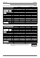
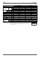

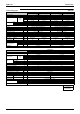
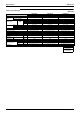
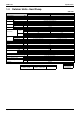

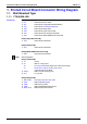
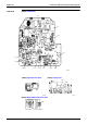
Table Of Contents
- Cover
- Table of Contents
- Part 1 List of Functions
- Part 2 Specifications
- Part 3 Printed Circuit Board Connector Wiring Diagram
- Part 4 Function and Control
- Part 5 Operation Manual
- Part 6 Service Diagnosis
- 1. Caution for Diagnosis
- 2. Problem Symptoms and Measures
- 3. Service Check Function
- 4. Code Indication on the Remote Controller
- 5. Troubleshooting
- 5.1 Indoor Units
- 5.2 Outdoor Units
- 5.3 Indoor Unit PCB Abnormality A1
- 5.4 Freeze-up Protection Control or High Pressure Control A5
- 5.5 Fan Motor or Related Abnormality A6
- 5.6 Thermistor or Related Abnormality (Indoor Unit) C4,C9
- 5.7 Front Panel Open / Close Fault C7
- 5.8 Signal Transmission Error (between Indoor and OutdoorUnit) U4
- 5.9 Unspecified Voltage (between Indoor and Outdoor Units) UA
- 5.10 Freeze-up Protection Control A5
- 5.11 Outdoor Unit PCB Abnormality E1
- 5.12 OL Activation (Compressor Overload) E5
- 5.13 Compressor Lock E6
- 5.14 DC Fan Lock E7
- 5.15 Input Over Current Detection E8
- 5.16 Discharge Pipe Temperature Control F3
- 5.17 High Pressure Control in Cooling F6
- 5.18 Compressor Sensor System Abnormality H0
- 5.19 Position Sensor Abnormality H6
- 5.20 CT or Related Abnormality H8
- 5.21 Thermistor or Related Abnormality (Outdoor Unit) P4,J3,J6,J8,J9,H9
- 5.22 Electrical Box Temperature Rise L3
- 5.23 Radiation Fin Temperature Rise L4
- 5.24 Output Over Current Detection L5
- 5.25 Insufficient Gas U0
- 5.26 Low-voltage Detection or Over-voltage Detection U2
- 5.27 Signal Transmission Error (on Outdoor Unit PCB) U7
- 5.28 Anti-icing Function in Other Rooms / UnspecifiedVoltage (between Indoor and Outdoor Units) UA,UH
- 6. Check
- Part 7 Removal Procedure
- Part 8 Others
- Part 9 Appendix
- Index
- Drawings & Flow Charts
SiBE12-713 Specifications
Specifications 35
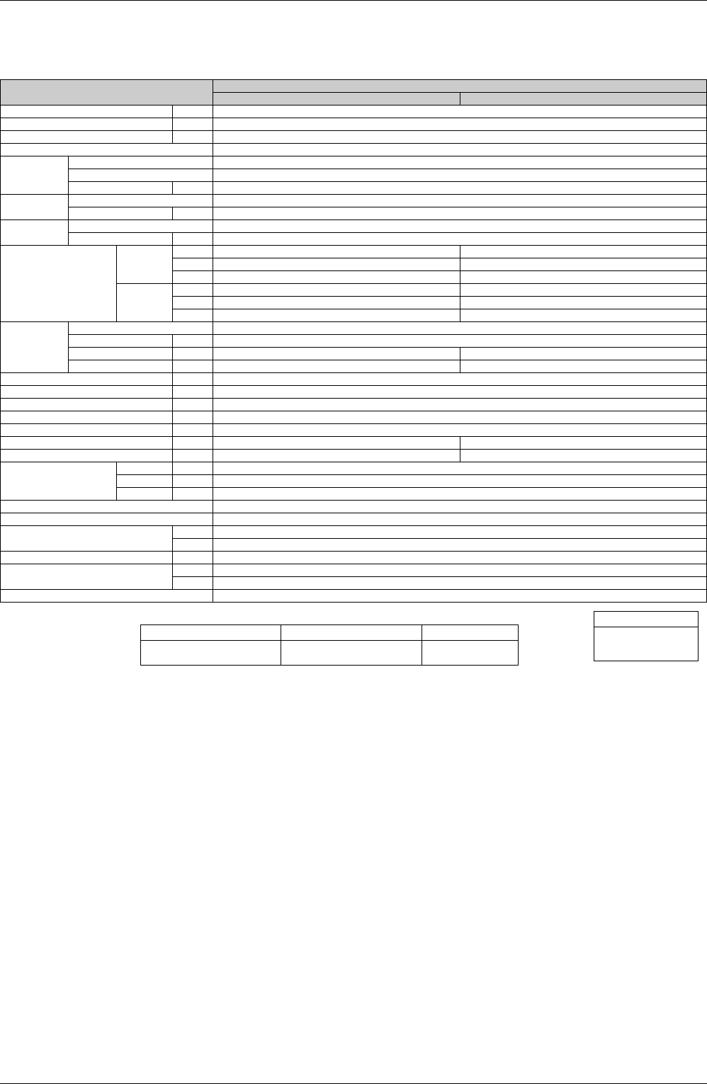
1.4 Outdoor Units - Heat Pump
50Hz 230V
Note:
1. The data are based on the conditions shown in the table below.
Model
4MXS68F2V1B
Cooling Heating
Cooling Capacity kW
—
Power Consumption W
—
Running Current A
—
Casing Color Ivory White
Compressor
Type Hermetically Sealed Swing Type
Model 2YC45DXD
Motor Output W 1,380
Refrigerant Oil
Model FVC50K
Charge L 0.65
Refrigerant
Type R-410A
Charge kg 2.6
Air Flow Rates
m³/min
H 52.7 46.4
M 49.4 44.5
L 43.5 16.3
cfm
H 1,861 1,638
M 1,744 1,571
L 1,536 576
Fan
Type Propeller
Motor Output W 53
Running Current A H: 0.20 / M: 0.16 / L: 0.10 H: 0.16 / M: 0.14 / L: 0.03
Power Consumption W H: 70 / M: 58 / L: 36 H: 55 / M: 48 / L: 10
Starting Current A 6.2
Dimensions (H×W×D) mm 735×936×300
Packaged Dimensions (H×W×D) mm 797×992×390
Weight kg 58
Gross Weight kg 63
Operation Sound dBA 48 49
Sound Power dBA 61
—
Piping Connection
Liquid mm
φ
6.4
×
4
Gas mm
φ
9.5
×
2
, φ
12.7
×
2
Drain mm
φ
18.0
Heat Insulation Both Liquid and Gas Pipes
No. of Wiring Connection 3 for Power Supply, 4 for Interunit Wiring
Max. Interunit Piping Length
m 60 (for Total of Each Room)
m 25 (for One Room)
Amount of Additional Charge g/m 20 (30m or more)
Max. Installation Height Difference
m 15 (between Indoor Unit and Outdoor Unit)
m 7.5 (between Indoor Units)
Drawing No. 3D056404
Conversion Formulae
kcal/h=kW×860
Btu/h=kW×3414
cfm=m³/min×35.3
Cooling Heating Piping Length
Indoor ; 27°CDB/19°CWB
Outdoor ; 35°CDB
Indoor ; 20°CDB
Outdoor ; 7°CDB/6°CWB
5m