
Specifications
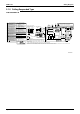
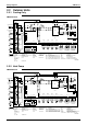
Table Of Contents
- Cover
- Table of Contents
- Part 1 List of Functions
- Part 2 Specifications
- Part 3 Printed Circuit Board Connector Wiring Diagram
- Part 4 Function and Control
- Part 5 Operation Manual
- Part 6 Service Diagnosis
- 1. Caution for Diagnosis
- 2. Problem Symptoms and Measures
- 3. Service Check Function
- 4. Code Indication on the Remote Controller
- 5. Troubleshooting
- 5.1 Indoor Units
- 5.2 Outdoor Units
- 5.3 Indoor Unit PCB Abnormality A1
- 5.4 Freeze-up Protection Control or High Pressure Control A5
- 5.5 Fan Motor or Related Abnormality A6
- 5.6 Thermistor or Related Abnormality (Indoor Unit) C4,C9
- 5.7 Front Panel Open / Close Fault C7
- 5.8 Signal Transmission Error (between Indoor and OutdoorUnit) U4
- 5.9 Unspecified Voltage (between Indoor and Outdoor Units) UA
- 5.10 Freeze-up Protection Control A5
- 5.11 Outdoor Unit PCB Abnormality E1
- 5.12 OL Activation (Compressor Overload) E5
- 5.13 Compressor Lock E6
- 5.14 DC Fan Lock E7
- 5.15 Input Over Current Detection E8
- 5.16 Discharge Pipe Temperature Control F3
- 5.17 High Pressure Control in Cooling F6
- 5.18 Compressor Sensor System Abnormality H0
- 5.19 Position Sensor Abnormality H6
- 5.20 CT or Related Abnormality H8
- 5.21 Thermistor or Related Abnormality (Outdoor Unit) P4,J3,J6,J8,J9,H9
- 5.22 Electrical Box Temperature Rise L3
- 5.23 Radiation Fin Temperature Rise L4
- 5.24 Output Over Current Detection L5
- 5.25 Insufficient Gas U0
- 5.26 Low-voltage Detection or Over-voltage Detection U2
- 5.27 Signal Transmission Error (on Outdoor Unit PCB) U7
- 5.28 Anti-icing Function in Other Rooms / UnspecifiedVoltage (between Indoor and Outdoor Units) UA,UH
- 6. Check
- Part 7 Removal Procedure
- Part 8 Others
- Part 9 Appendix
- Index
- Drawings & Flow Charts

SiBE12-713
Drawings & Flow Charts v
Drawings & Flow Charts
A
anti-icing function in other rooms .........................275
automatic air flow control .......................................65
automatic operation ................................................67
auto-swing ..............................................................62
B
buzzer PCB ............................................................44
C
capacitor voltage check ........................................283
check No.01 .........................................................276
check No.02 .........................................................276
check No.03 .........................................................276
check No.04 .........................................................277
check No.05 .........................................................278
check No.06 .........................................................279
check No.07 .........................................................280
check No.08 .........................................................281
check No.09 .........................................................281
check No.10 .........................................................282
check No.11 .........................................................282
check No.12 .........................................................283
check No.13 .........................................................283
check No.14 .........................................................284
check No.15 .........................................................284
check No.16 .........................................................285
comfort airflow mode ..............................................62
compressor lock ...................................................251
compressor overload ............................................250
compressor protection function ..............................87
compressor sensor system abnormality ...............258
control PCB (indoor unit)
...............................39, 41, 42, 44, 46, 47, 50, 53
cooling / heating mode lock ..................................101
CT or related abnormality .....................................261
D
DC fan lock ...........................................................252
defrost control ........................................................91
diagnosis mode ....................................................231
discharge pipe control ............................................88
discharge pipe temperature control ......................255
discharge pressure check ....................................281
display PCB ....................................39, 44, 48, 51, 53
E
econo mode ...........................................................70
electrical box temperature rise .............................265
electronic expansion valve check .........................277
electronic expansion valve control .........................92
F
fan motor connector output check ........................276
fan motor or related abnormality
ac motor ........................................................ 239
DC motor ...................................................... 240
four way valve performance check ...................... 278
freeze-up protection control .................. 89, 237, 247
frequency control ................................................... 83
frequency principle ................................................ 60
front panel open/close fault ................................. 243
function of thermistor
cooling only model .......................................... 80
heat pump model ............................................ 78
H
Hall IC check ....................................................... 285
heating peak-cut control ........................................ 89
high pressure control ........................................... 237
high pressure control in cooling .......................... 256
HOME LEAVE operation ....................................... 73
hot start function .................................................... 75
I
indoor unit PCB abnormality ............................... 236
input current control .............................................. 88
input over current detection ................................. 253
installation condition check ................................. 280
insufficient gas .................................................... 271
insufficient gas control ........................................... 96
INTELLIGENT EYE ............................................... 71
INTELLIGENT EYE sensor ................................. 322
INTELLIGENT EYE sensor PCB ......... 39, 42, 44, 46
inverter features .................................................... 61
inverter POWERFUL operation ............................. 74
inverter units refrigerant system check ................ 282
J
jumper settings .................................................... 321
L
limit switch continuity check ................................ 276
location of operation lamp ................................... 226
low-voltage detection .......................................... 273
M
main circuit electrolytic capacitor check .............. 284
main PCB (outdoor unit) ........................................ 57
main structural parts .............................................. 77
mode hierarchy ..................................................... 82
N
night set mode ....................................................... 69
O
OL activation ....................................................... 250
ON/OFF button on indoor unit ............................... 75
outdoor unit fan system check (with DC motor) .. 281