
Specifications
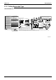
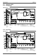
Table Of Contents
- Cover
- Table of Contents
- Part 1 List of Functions
- Part 2 Specifications
- Part 3 Printed Circuit Board Connector Wiring Diagram
- Part 4 Function and Control
- Part 5 Operation Manual
- Part 6 Service Diagnosis
- 1. Caution for Diagnosis
- 2. Problem Symptoms and Measures
- 3. Service Check Function
- 4. Code Indication on the Remote Controller
- 5. Troubleshooting
- 5.1 Indoor Units
- 5.2 Outdoor Units
- 5.3 Indoor Unit PCB Abnormality A1
- 5.4 Freeze-up Protection Control or High Pressure Control A5
- 5.5 Fan Motor or Related Abnormality A6
- 5.6 Thermistor or Related Abnormality (Indoor Unit) C4,C9
- 5.7 Front Panel Open / Close Fault C7
- 5.8 Signal Transmission Error (between Indoor and OutdoorUnit) U4
- 5.9 Unspecified Voltage (between Indoor and Outdoor Units) UA
- 5.10 Freeze-up Protection Control A5
- 5.11 Outdoor Unit PCB Abnormality E1
- 5.12 OL Activation (Compressor Overload) E5
- 5.13 Compressor Lock E6
- 5.14 DC Fan Lock E7
- 5.15 Input Over Current Detection E8
- 5.16 Discharge Pipe Temperature Control F3
- 5.17 High Pressure Control in Cooling F6
- 5.18 Compressor Sensor System Abnormality H0
- 5.19 Position Sensor Abnormality H6
- 5.20 CT or Related Abnormality H8
- 5.21 Thermistor or Related Abnormality (Outdoor Unit) P4,J3,J6,J8,J9,H9
- 5.22 Electrical Box Temperature Rise L3
- 5.23 Radiation Fin Temperature Rise L4
- 5.24 Output Over Current Detection L5
- 5.25 Insufficient Gas U0
- 5.26 Low-voltage Detection or Over-voltage Detection U2
- 5.27 Signal Transmission Error (on Outdoor Unit PCB) U7
- 5.28 Anti-icing Function in Other Rooms / UnspecifiedVoltage (between Indoor and Outdoor Units) UA,UH
- 6. Check
- Part 7 Removal Procedure
- Part 8 Others
- Part 9 Appendix
- Index
- Drawings & Flow Charts

SiBE12-713
iv Index
S38..........................................................................43
S40..................................................................56, 295
S41....................................................................45, 52
S42..........................................................................52
S46....................................................................45, 52
S47....................................................................45, 52
S48..........................................................................52
S49....................................................................45, 52
S51....................................................................45, 56
S52..................................................................56, 300
S6..........................................................38, 40, 43, 49
S7................................................................40, 47, 49
S70..................................................................56, 293
S8............................................................................43
S80..................................................................56, 296
S90..........................................................56, 296, 313
S92..........................................................56, 296, 313
S93..........................................................56, 296, 313
safety precautions .........................................106, 181
SC control ...............................................................94
self-diagnosis digital display....................................76
sensor malfunction detection ..................................96
sensor PCB (indoor unit).........................................53
service check function...........................................229
service monitor PCB ...............................................58
service PCB ....................................................53, 300
signal receiver PCB.........................39, 42, 44, 46, 51
signal receiving sign................................................75
signal transmission error .......................................244
signal transmission error (on outdoor unit PCB) ...274
sound blanket........................................................308
specifications...........................................................14
starting control
indoor unit.........................................................64
starting operation control.........................................94
stop valve cover ....................................................291
SW1 ....................................38, 43, 45, 47, 49, 52, 56
SW2 ............................................................49, 52, 56
SW3 ........................................................................56
SW4 ..................................................................52, 56
SW5 ........................................................................56
SW7 ........................................................................40
T
target discharge pipe temperature control ..............95
terminal board .......................................................304
test run from the remote controller ........................320
thermistor
discharge pipe thermistor .............78, 80, 95, 314
gas pipe thermistor .............................78, 80, 313
heat exchanger thermistor ..............................313
indoor heat exchanger thermistor...............79, 81
liquid pipe thermistor ................................79, 313
outdoor air thermistor .....................................313
outdoor heat exchanger thermistor.............78, 80
thermistor or related abnormality (indoor unit) ......242
thermistor or related abnormality (outdoor unit) ....263
thermistor resistance check ..................................279
thermostat control ...................................................68
TIMER operation ...........................................154, 196
titanium apatite photocatalytic air-purifying filter .....76
top panel .............................................................. 288
troubleshooting..................................................... 177
indoor units .................................................... 234
outdoor units .................................................. 235
troubleshooting with the LED indication ............... 227
troubleshooting with the operation lamp .............. 226
turning speed pulse input on the outdoor unit PCB
check............................................................. 284
U
U0......................................................................... 271
U2......................................................................... 273
U4......................................................................... 244
U7......................................................................... 274
UA ................................................................ 246, 275
UH ........................................................................ 275
unspecified voltage (between indoor and outdoor
units) ..................................................... 246, 275
V
V1....................................... 38, 40, 43, 45, 47, 49, 52
V100....................................................................... 56
V2........................................................................... 56
V3........................................................................... 56
V5........................................................................... 56
V9........................................................................... 56
varistor ......................... 38, 40, 43, 45, 47, 49, 52, 56
W
WEEKLY TIMER operation ............................ 76, 198
wide-angle louvers ................................................. 62
wiring diagrams .................................................... 331
wiring-error check................................................... 98
X
X14A ...................................................................... 54
X15A ...................................................................... 54
X17A ...................................................................... 54
X18A ...................................................................... 54
X19A ...................................................................... 54
X20A ...................................................................... 54
X24A ...................................................................... 54
X25A ...................................................................... 54
X26A ...................................................................... 54
X27A ...................................................................... 54
X29A ...................................................................... 54
X33A ...................................................................... 54
X35A ...................................................................... 54
X40A ...................................................................... 54
X5A ........................................................................ 54
X60A ...................................................................... 54
X61A ...................................................................... 54