
Specifications
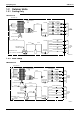
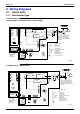
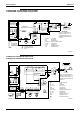

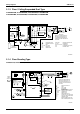
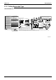
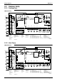
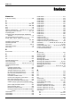
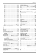
Table Of Contents
- Cover
- Table of Contents
- Part 1 List of Functions
- Part 2 Specifications
- Part 3 Printed Circuit Board Connector Wiring Diagram
- Part 4 Function and Control
- Part 5 Operation Manual
- Part 6 Service Diagnosis
- 1. Caution for Diagnosis
- 2. Problem Symptoms and Measures
- 3. Service Check Function
- 4. Code Indication on the Remote Controller
- 5. Troubleshooting
- 5.1 Indoor Units
- 5.2 Outdoor Units
- 5.3 Indoor Unit PCB Abnormality A1
- 5.4 Freeze-up Protection Control or High Pressure Control A5
- 5.5 Fan Motor or Related Abnormality A6
- 5.6 Thermistor or Related Abnormality (Indoor Unit) C4,C9
- 5.7 Front Panel Open / Close Fault C7
- 5.8 Signal Transmission Error (between Indoor and OutdoorUnit) U4
- 5.9 Unspecified Voltage (between Indoor and Outdoor Units) UA
- 5.10 Freeze-up Protection Control A5
- 5.11 Outdoor Unit PCB Abnormality E1
- 5.12 OL Activation (Compressor Overload) E5
- 5.13 Compressor Lock E6
- 5.14 DC Fan Lock E7
- 5.15 Input Over Current Detection E8
- 5.16 Discharge Pipe Temperature Control F3
- 5.17 High Pressure Control in Cooling F6
- 5.18 Compressor Sensor System Abnormality H0
- 5.19 Position Sensor Abnormality H6
- 5.20 CT or Related Abnormality H8
- 5.21 Thermistor or Related Abnormality (Outdoor Unit) P4,J3,J6,J8,J9,H9
- 5.22 Electrical Box Temperature Rise L3
- 5.23 Radiation Fin Temperature Rise L4
- 5.24 Output Over Current Detection L5
- 5.25 Insufficient Gas U0
- 5.26 Low-voltage Detection or Over-voltage Detection U2
- 5.27 Signal Transmission Error (on Outdoor Unit PCB) U7
- 5.28 Anti-icing Function in Other Rooms / UnspecifiedVoltage (between Indoor and Outdoor Units) UA,UH
- 6. Check
- Part 7 Removal Procedure
- Part 8 Others
- Part 9 Appendix
- Index
- Drawings & Flow Charts

SiBE12-713
Index iii
L5 ..........................................................................269
LED A............................38, 40, 43, 45, 47, 49, 52, 56
LED1 ...................................38, 40, 43, 47, 49, 52, 56
LED2 .............................38, 40, 43, 45, 47, 49, 52, 56
LED3 ...................................38, 40, 43, 45, 47, 49, 56
LED4 .................................................................45, 56
limit switch.......................................................45, 243
limit switch continuity check ..................................276
liquid compression protection function 2 .................90
liquid pipe thermistor ...............................................79
low-voltage detection ............................................273
M
main circuit electrolytic capacitor check ................284
main PCB (outdoor unit)..........................................57
main structural parts................................................77
mode hierarchy .......................................................82
mold proof air filter (prefilter) ...................................76
motor
reduction motor.................................................45
multi system ..................................................156, 203
N
names of parts ..............................................108, 183
night set mode.........................................................69
O
oil recovery function ................................................95
OL activation .........................................................250
ON/OFF button on indoor unit.................................75
opening limit ............................................................94
operation lamp ......................................................226
outdoor air thermistor ............................................298
outdoor heat exchanger thermistor ...................78, 80
outdoor unit fan system check (with DC motor) ....281
outdoor unit PCB abnormality ...............................249
outdoor unit quiet operation ..........................142, 194
output over current detection ................................269
over current .............................................................96
overload ..................................................................96
over-voltage detection...........................................273
P
P4..........................................................................263
PCB (ceiling suspended type).................................55
photocatalytic deodorizing filter...............................76
PI control .................................................................84
piping diagrams.....................................................324
position sensor abnormality ..................................260
power failure recovery function
.....................................38, 40, 43, 45, 47, 49, 52
power supply PCB...................................................50
power supply waveforms check ............................282
power transistor check ..........................................283
power-airflow dual flaps ..........................................62
POWERFUL operation..................................141, 193
POWERFUL operation mode................................100
preheating operation ...............................................86
preparation before operation.........................126, 186
pressure equalization control ..................................94
preventing indoor freezing.......................................97
printed circuit board (PCB)
buzzer PCB...................................................... 44
ceiling suspended type .................................... 55
control PCB.............................................. 47, 301
control PCB (indoor unit) ... 39, 42, 44, 46, 50, 53
display PCB ............................. 39, 44, 48, 51, 53
INTELLIGENT EYE sensor PCB ... 39, 42, 44, 46
main PCB (outdoor unit) .................................. 57
power supply PCB ........................................... 50
removal procedure......................................... 300
sensor PCB...................................................... 53
service monitor PCB ........................................ 58
service PCB ............................................. 53, 300
signal receiver PCB ................. 39, 42, 44, 46, 51
printed circuit board connector wiring diagram....... 38
priority room setting.............................................. 100
problem symptoms and measures ....................... 228
programme dry function ......................................... 66
propeller fan ......................................................... 306
R
radiation fin temperature rise ............................... 267
reduction motor .............................................. 45, 243
remote controller .................................................. 230
removal procedure
compressor .................................................... 317
distributor ....................................................... 315
electrical box.................................................. 292
electronic expansion valve coil ...................... 312
fan motor........................................................ 306
four way valve................................................ 316
four way valve coil ......................................... 312
panels and plates........................................... 288
PCB ............................................................... 300
propeller fan................................................... 306
sound blanket ................................................ 308
thermistor....................................................... 312
right side panel..................................................... 308
RTH1.............................................. 38, 40, 43, 45, 47
S
S1............................................. 38, 40, 43, 45, 47, 52
S10......................................................................... 56
S101....................................................................... 56
S102............................................................... 56, 300
S15......................................................................... 56
S20................................................................. 56, 294
S21....................... 38, 40, 43, 45, 47, 49, 52, 56, 294
S22................................................................. 56, 294
S23................................................................. 56, 294
S24......................................................................... 49
S25......................................................................... 49
S26........................................... 38, 40, 43, 47, 49, 52
S27................................................. 38, 40, 43, 49, 52
S28................................................................... 38, 43
S29................................................................... 38, 43
S31......................................................................... 49
S32........................................... 38, 40, 43, 45, 47, 49
S35............................................................. 38, 40, 43
S36................................................. 38, 40, 43, 45, 49
S37................................................................... 43, 49