
Specifications
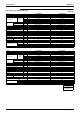
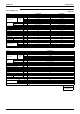
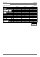
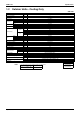
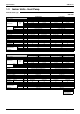

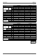

Table Of Contents
- Cover
- Table of Contents
- Part 1 List of Functions
- Part 2 Specifications
- Part 3 Printed Circuit Board Connector Wiring Diagram
- Part 4 Function and Control
- Part 5 Operation Manual
- Part 6 Service Diagnosis
- 1. Caution for Diagnosis
- 2. Problem Symptoms and Measures
- 3. Service Check Function
- 4. Code Indication on the Remote Controller
- 5. Troubleshooting
- 5.1 Indoor Units
- 5.2 Outdoor Units
- 5.3 Indoor Unit PCB Abnormality A1
- 5.4 Freeze-up Protection Control or High Pressure Control A5
- 5.5 Fan Motor or Related Abnormality A6
- 5.6 Thermistor or Related Abnormality (Indoor Unit) C4,C9
- 5.7 Front Panel Open / Close Fault C7
- 5.8 Signal Transmission Error (between Indoor and OutdoorUnit) U4
- 5.9 Unspecified Voltage (between Indoor and Outdoor Units) UA
- 5.10 Freeze-up Protection Control A5
- 5.11 Outdoor Unit PCB Abnormality E1
- 5.12 OL Activation (Compressor Overload) E5
- 5.13 Compressor Lock E6
- 5.14 DC Fan Lock E7
- 5.15 Input Over Current Detection E8
- 5.16 Discharge Pipe Temperature Control F3
- 5.17 High Pressure Control in Cooling F6
- 5.18 Compressor Sensor System Abnormality H0
- 5.19 Position Sensor Abnormality H6
- 5.20 CT or Related Abnormality H8
- 5.21 Thermistor or Related Abnormality (Outdoor Unit) P4,J3,J6,J8,J9,H9
- 5.22 Electrical Box Temperature Rise L3
- 5.23 Radiation Fin Temperature Rise L4
- 5.24 Output Over Current Detection L5
- 5.25 Insufficient Gas U0
- 5.26 Low-voltage Detection or Over-voltage Detection U2
- 5.27 Signal Transmission Error (on Outdoor Unit PCB) U7
- 5.28 Anti-icing Function in Other Rooms / UnspecifiedVoltage (between Indoor and Outdoor Units) UA,UH
- 6. Check
- Part 7 Removal Procedure
- Part 8 Others
- Part 9 Appendix
- Index
- Drawings & Flow Charts
Specifications SiBE12-713
24 Specifications
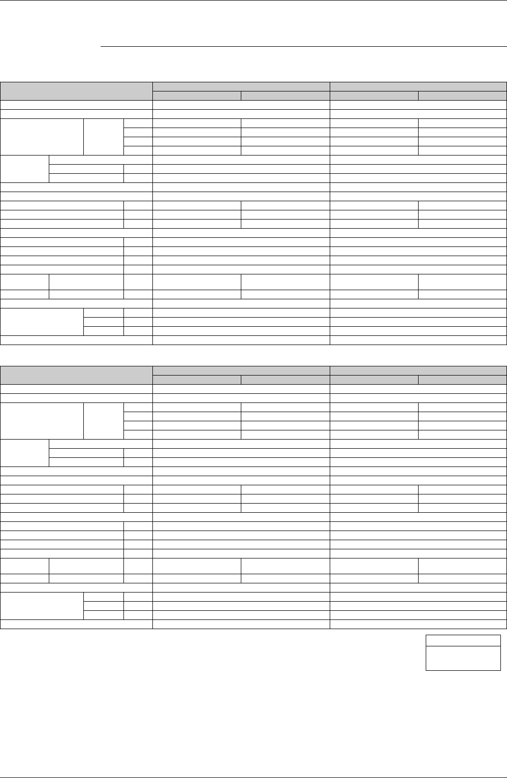
1.3 Indoor Units - Heat Pump
Wall Mounted Type
50Hz 230V
Model
FTXG25EV1BW FTXG25EV1BS
Cooling Heating Cooling Heating
Rated Capacity 2.5kW Class 2.5kW Class
Front Panel Color Mat Crystal White Mat Crystal Silver
Air Flow Rates
m³/min
(cfm)
H 7.7 (271) 9.0 (317) 7.7 (271) 9.0 (317)
M 6.1 (215) 7.9 (278) 6.1 (215) 7.9 (278)
L 4.7 (165) 6.7 (236) 4.7 (165) 6.7 (236)
SL 3.8 (134) 5.4 (190) 3.8 (134) 5.4 (190)
Fan
Type Cross Flow Fan Cross Flow Fan
Motor Output W 40 40
Speed Steps 5 Steps, Quiet, Auto 5 Steps, Quiet, Auto
Air Direction Control Right, Left, Horizontal, Downward Right, Left, Horizontal, Downward
Air Filter Removable-Washable-Mildew Proof Removable-Washable-Mildew Proof
Running Current (Rated) A 0.15-0.14-0.13 0.15-0.14-0.13 0.15-0.14-0.13 0.15-0.14-0.13
Power Consumption (Rated) W 30-30-30 30-30-30 30-30-30 30-30-30
Power Factor % 90.9-93.2-96.2 90.9-93.2-96.2 90.9-93.2-96.2 90.9-93.2-96.2
Temperature Control Microcomputer Control Microcomputer Control
Dimensions (H×W×D) mm 275×840×150 275×840×150
Packaged Dimensions (H×W×D) mm 222×894×345 222×894×345
Weight kg 9 9
Gross Weight kg 13 13
Operation
Sound
H/M/L/SL dBA 38/32/25/22 38/33/28/25 38/32/25/22 38/33/28/25
Sound Power H dBA 56 56 56 56
Heat Insulation Both Liquid and Gas Pipes Both Liquid and Gas Pipes
Piping Connection
Liquid mm
φ
6.4
φ
6.4
Gas mm
φ
9.5
φ
9.5
Drain mm
φ
18.0
φ
18.0
Drawing No. 3D051101 3D051102
Model
FTXG35EV1BW FTXG35EV1BS
Cooling Heating Cooling Heating
Rated Capacity 3.5kW Class 5.0kW Class
Front Panel Color Mat Crystal White Mat Crystal Silver
Air Flow Rates
m³/min
(cfm)
H 8.1 (285) 9.6 (338) 8.1 (285) 9.6 (338)
M 6.5 (229) 8.2 (289) 6.5 (229) 8.2 (289)
L 4.9 (173) 6.7 (236) 4.9 (173) 6.7 (236)
SL 4.1 (144) 5.9 (208) 4.1 (144) 5.9 (208)
Fan
Type Cross Flow Fan Cross Flow Fan
Motor Output W 40 40
Speed Steps 5 Steps, Quiet, Auto 5 Steps, Quiet, Auto
Air Direction Control Right, Left, Horizontal, Downward Right, Left, Horizontal, Downward
Air Filter Removable-Washable-Mildew Proof Removable-Washable-Mildew Proof
Running Current (Rated) A 0.15-0.14-0.13 0.15-0.14-0.13 0.15-0.14-0.13 0.15-0.14-0.13
Power Consumption (Rated) W 30-30-30 30-30-30 30-30-30 30-30-30
Power Factor % 90.9-93.2-96.2 90.9-93.2-96.2 90.9-93.2-96.2 90.9-93.2-96.2
Temperature Control Microcomputer Control Microcomputer Control
Dimensions (H×W×D) mm 275×840×150 275×840×150
Packaged Dimensions (H×W×D) mm 222×894×345 222×894×345
Weight kg 9 9
Gross Weight kg 13 13
Operation
Sound
H/M/L/SL dBA 39/33/26/23 39/34/29/26 39/33/26/23 39/34/29/26
Sound Power H dBA 57 57 57 57
Heat Insulation Both Liquid and Gas Pipes Both Liquid and Gas Pipes
Piping Connection
Liquid mm
φ
6.4
φ
6.4
Gas mm
φ
9.5
φ
12.7
Drain mm
φ
18.0
φ
18.0
Drawing No. 3D051103 3D051104
Conversion Formulae
kcal/h=kW×860
Btu/h=kW×3414
cfm=m³/min×35.3