
Specifications
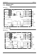
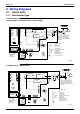
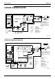

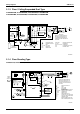
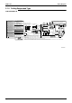
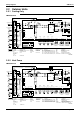
Table Of Contents
- Cover
- Table of Contents
- Part 1 List of Functions
- Part 2 Specifications
- Part 3 Printed Circuit Board Connector Wiring Diagram
- Part 4 Function and Control
- Part 5 Operation Manual
- Part 6 Service Diagnosis
- 1. Caution for Diagnosis
- 2. Problem Symptoms and Measures
- 3. Service Check Function
- 4. Code Indication on the Remote Controller
- 5. Troubleshooting
- 5.1 Indoor Units
- 5.2 Outdoor Units
- 5.3 Indoor Unit PCB Abnormality A1
- 5.4 Freeze-up Protection Control or High Pressure Control A5
- 5.5 Fan Motor or Related Abnormality A6
- 5.6 Thermistor or Related Abnormality (Indoor Unit) C4,C9
- 5.7 Front Panel Open / Close Fault C7
- 5.8 Signal Transmission Error (between Indoor and OutdoorUnit) U4
- 5.9 Unspecified Voltage (between Indoor and Outdoor Units) UA
- 5.10 Freeze-up Protection Control A5
- 5.11 Outdoor Unit PCB Abnormality E1
- 5.12 OL Activation (Compressor Overload) E5
- 5.13 Compressor Lock E6
- 5.14 DC Fan Lock E7
- 5.15 Input Over Current Detection E8
- 5.16 Discharge Pipe Temperature Control F3
- 5.17 High Pressure Control in Cooling F6
- 5.18 Compressor Sensor System Abnormality H0
- 5.19 Position Sensor Abnormality H6
- 5.20 CT or Related Abnormality H8
- 5.21 Thermistor or Related Abnormality (Outdoor Unit) P4,J3,J6,J8,J9,H9
- 5.22 Electrical Box Temperature Rise L3
- 5.23 Radiation Fin Temperature Rise L4
- 5.24 Output Over Current Detection L5
- 5.25 Insufficient Gas U0
- 5.26 Low-voltage Detection or Over-voltage Detection U2
- 5.27 Signal Transmission Error (on Outdoor Unit PCB) U7
- 5.28 Anti-icing Function in Other Rooms / UnspecifiedVoltage (between Indoor and Outdoor Units) UA,UH
- 6. Check
- Part 7 Removal Procedure
- Part 8 Others
- Part 9 Appendix
- Index
- Drawings & Flow Charts

SiBE12-713
Index i
Index
Numerics
3 minutes stand-by..................................................86
A
A1..........................................................................236
A5..................................................................237, 247
A6..................................................................239, 240
AC1 .........................................................................56
AC2 .........................................................................56
address setting jumper........38, 40, 43, 45, 47, 49, 52
adjusting the air flow direction.......................131, 191
air purifying filter......................................................76
air purifying filter with photocatalytic deodorizing
function ............................................................76
anti-icing function in other rooms ..........................275
AUTO · DRY · COOL · HEAT · FAN operation
...............................................................129, 189
automatic air flow control ........................................65
automatic operation.................................................67
auto-restart........................................................38, 45
auto-restart function ................................................76
auto-swing...............................................................62
B
buzzer PCB .............................................................44
C
C4..........................................................................242
C7..........................................................................243
C9..........................................................................242
capacitor voltage check.........................................283
care and cleaning..........................................158, 205
centralized control .....................38, 40, 43, 45, 47, 49
changing operation room ........................................94
check
capacitor voltage check ..................................283
discharge pressure check...............................281
electronic expansion valve check ...................277
fan motor connector output check ..................276
four way valve performance check .................278
Hall IC check ..................................................285
installation condition check .............................280
inverter units refrigerant system check...........282
limit switch continuity check............................276
main circuit electrolytic capacitor check..........284
outdoor unit fan system check (with DC motor)
...........................................................281
power supply waveforms check......................282
power transistor check....................................283
thermistor resistance check............................279
turning speed pulse input on the outdoor unit PCB
check .................................................284
check No.01 ..........................................................276
check No.02 ..........................................................276
check No.03 ..........................................................276
check No.04 ......................................................... 277
check No.05 ......................................................... 278
check No.06 ......................................................... 279
check No.07 ......................................................... 280
check No.08 ......................................................... 281
check No.09 ......................................................... 281
check No.10 ......................................................... 282
check No.11 ......................................................... 282
check No.12 ......................................................... 283
check No.13 ......................................................... 283
check No.14 ......................................................... 284
check No.15 ......................................................... 284
check No.16 ......................................................... 285
compressor .......................................................... 317
compressor lock ................................................... 251
compressor overload............................................ 250
compressor protection function .............................. 87
compressor sensor system abnormality............... 258
connectors.................... 38, 40, 43, 45, 47, 49, 52, 56
control PCB .................................................... 47, 301
control PCB (indoor unit).......... 39, 42, 44, 46, 50, 53
cooling / heating mode lock.................................. 101
CT or related abnormality..................................... 261
D
DC fan lock........................................................... 252
defrost control ........................................................ 91
diagnosis mode .................................................... 231
discharge grille ..................................................... 291
discharge pipe........................................................ 95
discharge pipe control ............................................ 88
discharge pipe temperature control................ 95, 255
discharge pipe thermistor ........................... 78, 80, 95
discharge pressure check .................................... 281
display PCB.................................... 39, 44, 48, 51, 53
distributor ............................................................. 315
E
E1......................................................................... 249
E5......................................................................... 250
E6......................................................................... 251
E7......................................................................... 252
E8......................................................................... 253
econo mode ........................................................... 70
econo operation ........................................... 143, 195
econo-mode-proof setting .................................... 101
electrical box ........................................................ 292
electrical box temperature rise ............................. 265
electronic expansion valve check......................... 277
electronic expansion valve coil............................. 312
electronic expansion valve control ......................... 92
error codes
A1 .................................................................. 236
A5 .......................................................... 237, 247
A6 .......................................................... 239, 240