
Specifications
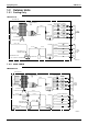
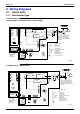
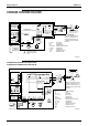

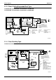
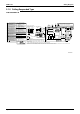
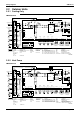
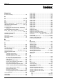
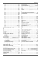
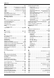
Table Of Contents
- Cover
- Table of Contents
- Part 1 List of Functions
- Part 2 Specifications
- Part 3 Printed Circuit Board Connector Wiring Diagram
- Part 4 Function and Control
- Part 5 Operation Manual
- Part 6 Service Diagnosis
- 1. Caution for Diagnosis
- 2. Problem Symptoms and Measures
- 3. Service Check Function
- 4. Code Indication on the Remote Controller
- 5. Troubleshooting
- 5.1 Indoor Units
- 5.2 Outdoor Units
- 5.3 Indoor Unit PCB Abnormality A1
- 5.4 Freeze-up Protection Control or High Pressure Control A5
- 5.5 Fan Motor or Related Abnormality A6
- 5.6 Thermistor or Related Abnormality (Indoor Unit) C4,C9
- 5.7 Front Panel Open / Close Fault C7
- 5.8 Signal Transmission Error (between Indoor and OutdoorUnit) U4
- 5.9 Unspecified Voltage (between Indoor and Outdoor Units) UA
- 5.10 Freeze-up Protection Control A5
- 5.11 Outdoor Unit PCB Abnormality E1
- 5.12 OL Activation (Compressor Overload) E5
- 5.13 Compressor Lock E6
- 5.14 DC Fan Lock E7
- 5.15 Input Over Current Detection E8
- 5.16 Discharge Pipe Temperature Control F3
- 5.17 High Pressure Control in Cooling F6
- 5.18 Compressor Sensor System Abnormality H0
- 5.19 Position Sensor Abnormality H6
- 5.20 CT or Related Abnormality H8
- 5.21 Thermistor or Related Abnormality (Outdoor Unit) P4,J3,J6,J8,J9,H9
- 5.22 Electrical Box Temperature Rise L3
- 5.23 Radiation Fin Temperature Rise L4
- 5.24 Output Over Current Detection L5
- 5.25 Insufficient Gas U0
- 5.26 Low-voltage Detection or Over-voltage Detection U2
- 5.27 Signal Transmission Error (on Outdoor Unit PCB) U7
- 5.28 Anti-icing Function in Other Rooms / UnspecifiedVoltage (between Indoor and Outdoor Units) UA,UH
- 6. Check
- Part 7 Removal Procedure
- Part 8 Others
- Part 9 Appendix
- Index
- Drawings & Flow Charts
SiBE12-713 Wiring Diagrams
Appendix 331
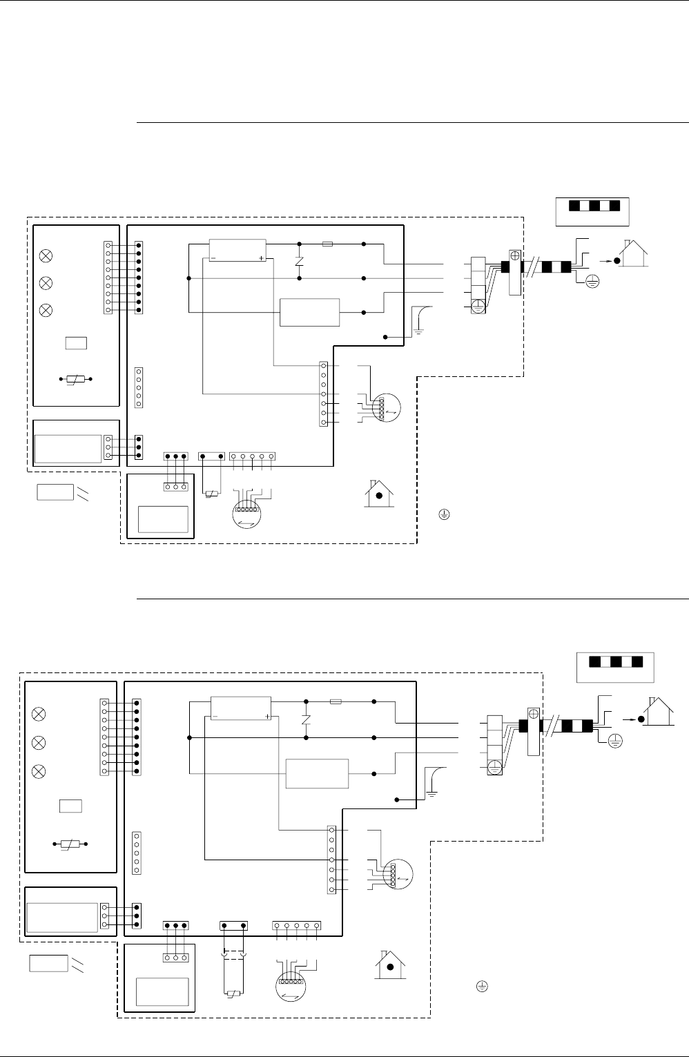
2. Wiring Diagrams
2.1 Indoor Units
2.1.1 Wall Mounted Type
FTKS20D3VMW(L), FTKS25D3VMW(L), FTKS35D3VMW(L)
FTXS20D3VMW(L), FTXS25D3VMW(L), FTXS35D3VMW(L)
FTKS50D2V1W(L), FTXS50D2V1W(L)
: FRAME GROUND
: FUSE
: PILOT LAMP
: FAN MOTOR
: PRINTED CIRCUIT BOARD
R1T, R2T
: CONNECTOR
: OPERATION SWITCH
: TERMINAL STRIP
CONTROLLER
WIRELESS
PCB3
PCB4
INTELLIGENT EYE
REMOTE
SENSOR
LED2
LED3
H2P
H3P
LED1
H1P
S1W
R1T
t°
S27
S36
S26
PCB2
S35
S21
RECEIVER
HA
SIGNAL
PCB1
S29
S28
R2T
S32
t°
∼
RECTIFIER
1
RED
M1S
M
S6
ORG
∼
YLW
PNK
5
BLU
V1
TRANSMISSION
CIRCUIT
7
1
3.15A
S1
F1U
WHT
BRN
RED
BLU
ORG
H2
H3
H1
INDOOR
M1F
FG
M
GRN
: SWING MOTORM1S
F1U
WHT
RED
/
BLK
M1F
H1P~H3P
S1~S38
FG
YLW
X1M
S1W
PCB1~PCB4
X1M
3
2
1
: PROTECTIVE EARTH
: THERMISTOR
THE MAIN POWER SUPPLY IS
ON AGAIN.
TURNED OFF AND THEN BACK
NOTE THAT OPERATION WILL
RESTART AUTOMATICALLY IF
FIELD WIRING.
CAUTION
2
3
1
OUTDOOR
3D051268A
CONTROLLER
WIRELESS
PCB3
PCB4
INTELLIGENT EYE
REMOTE
SENSOR
LED2
LED3
H2P
H3P
LED1
H1P
S1W
R1T
t°
S27
S36
S26
PCB2
S35
S21
RECEIVER
HA
SIGNAL
PCB1
S29
S28
X41A
~
RECTIFIER
S32
R2T
t°
~
1
RED
M1S
V1
M
TRANSMISSION
S6
ORG
CIRCUIT
YLW
PNK
5
7
1
BLU
3.15A
S1
F1U
WHT
BRN
RED
BLU
ORG
H2
H3
H1
INDOOR
M1F
FG
M
M1S
R1T, R2T
GRN
H1P~H3P
S1W
S1~S38, X41A
F1U
M1F
FG
X1M
PCB1~PCB4
WHT
RED
/
BLK
YLW
X1M
3
2
1
: CONNECTOR
: OPERATION SWITCH
: PILOT LAMP
: FUSE
: FAN MOTOR
: PROTECTIVE EARTH
: TERMINAL STRIP
: THERMISTOR
: FRAME GROUND
: SWING MOTOR
: PRINTED CIRCUIT BOARD
THE MAIN POWER SUPPLY IS
ON AGAIN.
TURNED OFF AND THEN BACK
NOTE THAT OPERATION WILL
RESTART AUTOMATICALLY IF
FIELD WIRING.
CAUTION
3
2
1
OUTDOOR
3D051652