
Specifications
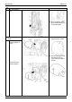
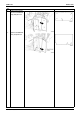
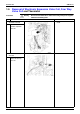
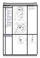
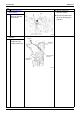
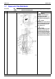
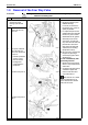
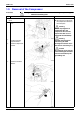
Table Of Contents
- Cover
- Table of Contents
- Part 1 List of Functions
- Part 2 Specifications
- Part 3 Printed Circuit Board Connector Wiring Diagram
- Part 4 Function and Control
- Part 5 Operation Manual
- Part 6 Service Diagnosis
- 1. Caution for Diagnosis
- 2. Problem Symptoms and Measures
- 3. Service Check Function
- 4. Code Indication on the Remote Controller
- 5. Troubleshooting
- 5.1 Indoor Units
- 5.2 Outdoor Units
- 5.3 Indoor Unit PCB Abnormality A1
- 5.4 Freeze-up Protection Control or High Pressure Control A5
- 5.5 Fan Motor or Related Abnormality A6
- 5.6 Thermistor or Related Abnormality (Indoor Unit) C4,C9
- 5.7 Front Panel Open / Close Fault C7
- 5.8 Signal Transmission Error (between Indoor and OutdoorUnit) U4
- 5.9 Unspecified Voltage (between Indoor and Outdoor Units) UA
- 5.10 Freeze-up Protection Control A5
- 5.11 Outdoor Unit PCB Abnormality E1
- 5.12 OL Activation (Compressor Overload) E5
- 5.13 Compressor Lock E6
- 5.14 DC Fan Lock E7
- 5.15 Input Over Current Detection E8
- 5.16 Discharge Pipe Temperature Control F3
- 5.17 High Pressure Control in Cooling F6
- 5.18 Compressor Sensor System Abnormality H0
- 5.19 Position Sensor Abnormality H6
- 5.20 CT or Related Abnormality H8
- 5.21 Thermistor or Related Abnormality (Outdoor Unit) P4,J3,J6,J8,J9,H9
- 5.22 Electrical Box Temperature Rise L3
- 5.23 Radiation Fin Temperature Rise L4
- 5.24 Output Over Current Detection L5
- 5.25 Insufficient Gas U0
- 5.26 Low-voltage Detection or Over-voltage Detection U2
- 5.27 Signal Transmission Error (on Outdoor Unit PCB) U7
- 5.28 Anti-icing Function in Other Rooms / UnspecifiedVoltage (between Indoor and Outdoor Units) UA,UH
- 6. Check
- Part 7 Removal Procedure
- Part 8 Others
- Part 9 Appendix
- Index
- Drawings & Flow Charts
Outdoor Unit SiBE12-713
316 Removal Procedure
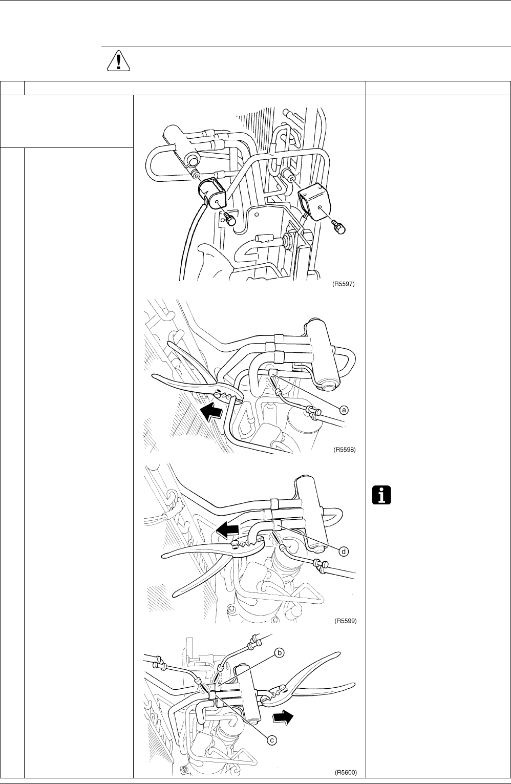
1.8 Removal of the Four Way Valve
Procedure Warning Be sure to wait 10 minutes or more after turning off all power supplies
before disassembling work.
Step
Procedure Points
Be sure to apply nitrogen
replacement when
heating up the brazed
part.
Cautions for restoration
1. Restore the piping by non-
oxidation brazing.
In case of you cannot use
the nitrogen gas, restore as
quickly as possible.
2. It is required to prevent the
carbonization of the oil inside
the four way valve and the
deterioration of the gaskets
affected by heat. For the
sake of this, wrap the four
way valve with wet cloth and
provide water so that the
cloth will not be dried and
avoid excessive heating.
(Keep below 120°C)
Be careful so as not to break
the pipes by pressing it
excessively by pliers when
withdrawing it.
In case of the difficulty with
gas brazing machine
1. Disconnect the brazed part
where is easy to disconnect
and restore.
2. Cut pipes on the main unit by
a miniature copper tube
cutter in order to make it
easy to disconnect.
Note: Do not use a metal
saw for cutting pipes by all
means because the sawdust
come into the circuit.
1
Loosen the 1 screw to
remove the four way
valve coil.
2
Heat up the 4 brazed
part of the four way
valve. First, disconnect
the part "a".
Provide a protective
sheet or a steel
plate so that the
brazing flame
cannot influence
peripheries.
3
Disconnect the part "d".
4
Disconnect the part "b"
and "c".