
Specifications
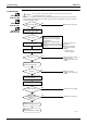
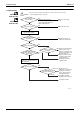
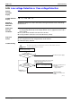
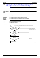
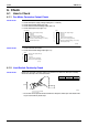
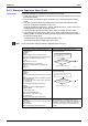
Table Of Contents
- Cover
- Table of Contents
- Part 1 List of Functions
- Part 2 Specifications
- Part 3 Printed Circuit Board Connector Wiring Diagram
- Part 4 Function and Control
- Part 5 Operation Manual
- Part 6 Service Diagnosis
- 1. Caution for Diagnosis
- 2. Problem Symptoms and Measures
- 3. Service Check Function
- 4. Code Indication on the Remote Controller
- 5. Troubleshooting
- 5.1 Indoor Units
- 5.2 Outdoor Units
- 5.3 Indoor Unit PCB Abnormality A1
- 5.4 Freeze-up Protection Control or High Pressure Control A5
- 5.5 Fan Motor or Related Abnormality A6
- 5.6 Thermistor or Related Abnormality (Indoor Unit) C4,C9
- 5.7 Front Panel Open / Close Fault C7
- 5.8 Signal Transmission Error (between Indoor and OutdoorUnit) U4
- 5.9 Unspecified Voltage (between Indoor and Outdoor Units) UA
- 5.10 Freeze-up Protection Control A5
- 5.11 Outdoor Unit PCB Abnormality E1
- 5.12 OL Activation (Compressor Overload) E5
- 5.13 Compressor Lock E6
- 5.14 DC Fan Lock E7
- 5.15 Input Over Current Detection E8
- 5.16 Discharge Pipe Temperature Control F3
- 5.17 High Pressure Control in Cooling F6
- 5.18 Compressor Sensor System Abnormality H0
- 5.19 Position Sensor Abnormality H6
- 5.20 CT or Related Abnormality H8
- 5.21 Thermistor or Related Abnormality (Outdoor Unit) P4,J3,J6,J8,J9,H9
- 5.22 Electrical Box Temperature Rise L3
- 5.23 Radiation Fin Temperature Rise L4
- 5.24 Output Over Current Detection L5
- 5.25 Insufficient Gas U0
- 5.26 Low-voltage Detection or Over-voltage Detection U2
- 5.27 Signal Transmission Error (on Outdoor Unit PCB) U7
- 5.28 Anti-icing Function in Other Rooms / UnspecifiedVoltage (between Indoor and Outdoor Units) UA,UH
- 6. Check
- Part 7 Removal Procedure
- Part 8 Others
- Part 9 Appendix
- Index
- Drawings & Flow Charts
Troubleshooting SiBE12-713
272 Service Diagnosis
Troubleshooting
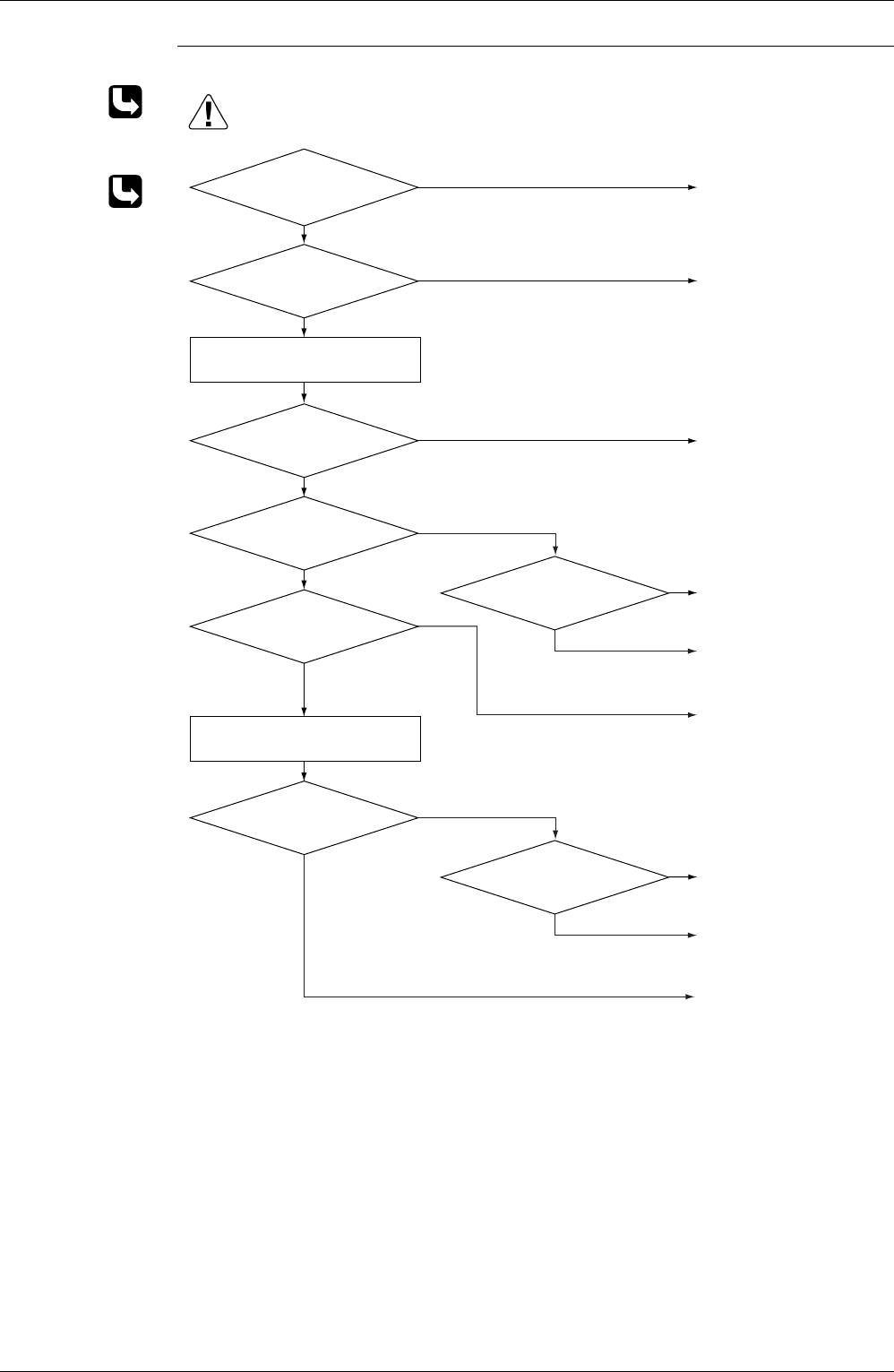
Check No.04
Refer to P.277
Check No.06
Refer to P.279
Reconnect in position.
Open the stop valve.
Repair the pipe flare or
replace the square union.
Check the power transistor
harness for looseness.
Correct it as required. Also
replace cracked pipe if any.
Check the pipes for
improper contact. Correct
as required. Also replace
cracked pipe if any.
Replace the electronic
expansion valve.
Replace the room
temperature or outdoor air
thermistor, or the indoor
unit or outdoor unit heat
exchanger thermistor.
(1) Replace the PCB.
(2)
Replace the compressor.
Procedure complete
(R5150)
Caution
Be sure to turn off power switch before connect or disconnect connector,
or parts damage may be occurred.
Any thermistor
disconnected?
YES
Malfunctioning
NO
Stop valve closed?
NO
YES
YES
NO
Gas shortage error again?
Functioning
Check No. 06
Check the thermistors.
YES
NO
Oil oozing at internal piping?
NO
YES
Check No. 04
Electronic expansion valve
functioning?
YES
NO
Oil oozing at relay pipe
connections?
Check for gas leakage.
Change for a specified amount of
fresh refrigerant.
NO
YES
Compressor vibrating
too much?
* Discharge pipe thermistor
* Indoor / outdoor unit heat exchanger thermistor
* Room temperature thermistor
* Outdoor air thermistor