
Specifications
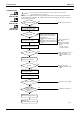
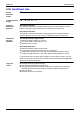
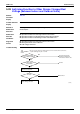
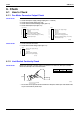
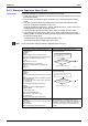
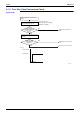
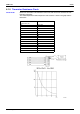
Table Of Contents
- Cover
- Table of Contents
- Part 1 List of Functions
- Part 2 Specifications
- Part 3 Printed Circuit Board Connector Wiring Diagram
- Part 4 Function and Control
- Part 5 Operation Manual
- Part 6 Service Diagnosis
- 1. Caution for Diagnosis
- 2. Problem Symptoms and Measures
- 3. Service Check Function
- 4. Code Indication on the Remote Controller
- 5. Troubleshooting
- 5.1 Indoor Units
- 5.2 Outdoor Units
- 5.3 Indoor Unit PCB Abnormality A1
- 5.4 Freeze-up Protection Control or High Pressure Control A5
- 5.5 Fan Motor or Related Abnormality A6
- 5.6 Thermistor or Related Abnormality (Indoor Unit) C4,C9
- 5.7 Front Panel Open / Close Fault C7
- 5.8 Signal Transmission Error (between Indoor and OutdoorUnit) U4
- 5.9 Unspecified Voltage (between Indoor and Outdoor Units) UA
- 5.10 Freeze-up Protection Control A5
- 5.11 Outdoor Unit PCB Abnormality E1
- 5.12 OL Activation (Compressor Overload) E5
- 5.13 Compressor Lock E6
- 5.14 DC Fan Lock E7
- 5.15 Input Over Current Detection E8
- 5.16 Discharge Pipe Temperature Control F3
- 5.17 High Pressure Control in Cooling F6
- 5.18 Compressor Sensor System Abnormality H0
- 5.19 Position Sensor Abnormality H6
- 5.20 CT or Related Abnormality H8
- 5.21 Thermistor or Related Abnormality (Outdoor Unit) P4,J3,J6,J8,J9,H9
- 5.22 Electrical Box Temperature Rise L3
- 5.23 Radiation Fin Temperature Rise L4
- 5.24 Output Over Current Detection L5
- 5.25 Insufficient Gas U0
- 5.26 Low-voltage Detection or Over-voltage Detection U2
- 5.27 Signal Transmission Error (on Outdoor Unit PCB) U7
- 5.28 Anti-icing Function in Other Rooms / UnspecifiedVoltage (between Indoor and Outdoor Units) UA,UH
- 6. Check
- Part 7 Removal Procedure
- Part 8 Others
- Part 9 Appendix
- Index
- Drawings & Flow Charts

SiBE12-713 Troubleshooting
Service Diagnosis 271
5.25 Insufficient Gas
Remote
Controller
Display
U0
Outdoor Unit LED
Display
A
5
1
1
2
1
3
4
4
4
Method of
Malfunction
Detection
Gas shortage detection I:
Gas shortage is detected by checking the input current value and the compressor running
frequency. If the gas is short, the input current is smaller than the normal value.
Gas shortage detection II:
Gas shortage is detected by checking the discharge temperature and the opening of the
electronic expansion valve. If the gas is short, the discharge temperature tends to rise.
Malfunction
Decision
Conditions
Gas shortage detection I (typical value):
The following conditions continue for 7 minutes.
DC current
≤
0.035 × output frequency + 0.5
Output frequency > 55 (Hz)
Gas shortage detection II:
The following conditions continue for 80 seconds.
Target opening of the electronic expansion valve
≥
450 (pulse)
Cooling: discharge temperature > 255 / 256 × target discharge temperature +20 (°C)
Heating: discharge temperature > 255 / 256 × target discharge temperature +40 (°C)
If a gas shortage error takes place 4 times straight, the system will be shut down. The error
counter will reset itself if this or any other error does not occur during the following 60-minute
compressor running time (total time).
Supposed
Causes
Refrigerant shortage (refrigerant leakage)
Poor compression performance of compressor
Discharge pipe thermistor disconnected, or indoor unit or outdoor unit heat exchanger
thermistor disconnected, room or outside air temperature thermistor disconnected
Stop valve closed
Electronic expansion valve defective