
Specifications
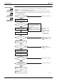
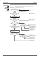
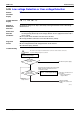
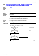
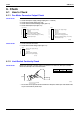
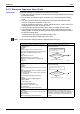
Table Of Contents
- Cover
- Table of Contents
- Part 1 List of Functions
- Part 2 Specifications
- Part 3 Printed Circuit Board Connector Wiring Diagram
- Part 4 Function and Control
- Part 5 Operation Manual
- Part 6 Service Diagnosis
- 1. Caution for Diagnosis
- 2. Problem Symptoms and Measures
- 3. Service Check Function
- 4. Code Indication on the Remote Controller
- 5. Troubleshooting
- 5.1 Indoor Units
- 5.2 Outdoor Units
- 5.3 Indoor Unit PCB Abnormality A1
- 5.4 Freeze-up Protection Control or High Pressure Control A5
- 5.5 Fan Motor or Related Abnormality A6
- 5.6 Thermistor or Related Abnormality (Indoor Unit) C4,C9
- 5.7 Front Panel Open / Close Fault C7
- 5.8 Signal Transmission Error (between Indoor and OutdoorUnit) U4
- 5.9 Unspecified Voltage (between Indoor and Outdoor Units) UA
- 5.10 Freeze-up Protection Control A5
- 5.11 Outdoor Unit PCB Abnormality E1
- 5.12 OL Activation (Compressor Overload) E5
- 5.13 Compressor Lock E6
- 5.14 DC Fan Lock E7
- 5.15 Input Over Current Detection E8
- 5.16 Discharge Pipe Temperature Control F3
- 5.17 High Pressure Control in Cooling F6
- 5.18 Compressor Sensor System Abnormality H0
- 5.19 Position Sensor Abnormality H6
- 5.20 CT or Related Abnormality H8
- 5.21 Thermistor or Related Abnormality (Outdoor Unit) P4,J3,J6,J8,J9,H9
- 5.22 Electrical Box Temperature Rise L3
- 5.23 Radiation Fin Temperature Rise L4
- 5.24 Output Over Current Detection L5
- 5.25 Insufficient Gas U0
- 5.26 Low-voltage Detection or Over-voltage Detection U2
- 5.27 Signal Transmission Error (on Outdoor Unit PCB) U7
- 5.28 Anti-icing Function in Other Rooms / UnspecifiedVoltage (between Indoor and Outdoor Units) UA,UH
- 6. Check
- Part 7 Removal Procedure
- Part 8 Others
- Part 9 Appendix
- Index
- Drawings & Flow Charts
Troubleshooting SiBE12-713
270 Service Diagnosis
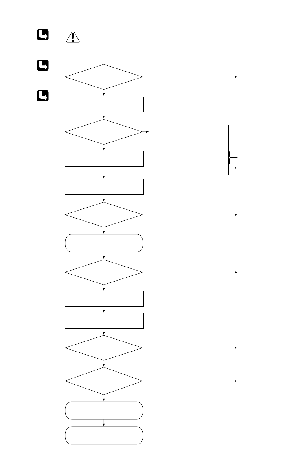
Troubleshooting
Check No.07
Refer to P.280
Check No.08
Refer to P.281
Check No.13
Refer to P.283
Fully open the stop valve.
Keep on using as it is
(monitor).
Check the electricals'
connectors and other
fittings.
∗ Inverter checker
Part No.: 1225477
Correct the power supply or
replace the PM1.
(Replace the outdoor unit
PCB.)
Replace the PM1.
(Replace the outdoor unit
PCB.)
Correct the power supply.
Replace the compressor.
(R5149)
Caution
Be sure to turn off power switch before connect or disconnect connector,
or parts damage may be occurred.
Stop valve fully open?
NO
YES
∗ An output over-current may result from wrong internal wiring. If the wires have been disconnected and
reconnected for part replacement, for example, and the system is interrupted by an output over-current,
take the following procedure.
Error again?
NO
YES
NO
YES
Voltage as rated?
YES
NO
Short-circuit
or breakage between
compressor's coil
phases?
NO
YES
Normal?
YES
NO
Any LED off?
Turn off the power and turn it on
again to get the system started.
See if the same error occurs.
Turn off the power and disconnect
the harnesses U, V and W.
Monitor the supply voltage,
discharge and suction pressures,
and other factors for a long term.
Possible causes
z Instantaneous supply voltage
drop
z Compressor motor overloaded
z Contact-induced electrical short-
circuit
Check with the inverter checker (∗).
Turn off the power, and reconnect
the harnesses. Turn on the power
again and get restarted.
Check the supply voltage.
Check No. 13
Check the power transistor.
Check No. 08
Check the discharge pressure.
Check No. 07
Check the installation condition.