
Specifications
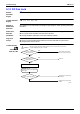
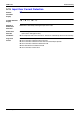
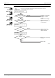
Table Of Contents
- Cover
- Table of Contents
- Part 1 List of Functions
- Part 2 Specifications
- Part 3 Printed Circuit Board Connector Wiring Diagram
- Part 4 Function and Control
- Part 5 Operation Manual
- Part 6 Service Diagnosis
- 1. Caution for Diagnosis
- 2. Problem Symptoms and Measures
- 3. Service Check Function
- 4. Code Indication on the Remote Controller
- 5. Troubleshooting
- 5.1 Indoor Units
- 5.2 Outdoor Units
- 5.3 Indoor Unit PCB Abnormality A1
- 5.4 Freeze-up Protection Control or High Pressure Control A5
- 5.5 Fan Motor or Related Abnormality A6
- 5.6 Thermistor or Related Abnormality (Indoor Unit) C4,C9
- 5.7 Front Panel Open / Close Fault C7
- 5.8 Signal Transmission Error (between Indoor and OutdoorUnit) U4
- 5.9 Unspecified Voltage (between Indoor and Outdoor Units) UA
- 5.10 Freeze-up Protection Control A5
- 5.11 Outdoor Unit PCB Abnormality E1
- 5.12 OL Activation (Compressor Overload) E5
- 5.13 Compressor Lock E6
- 5.14 DC Fan Lock E7
- 5.15 Input Over Current Detection E8
- 5.16 Discharge Pipe Temperature Control F3
- 5.17 High Pressure Control in Cooling F6
- 5.18 Compressor Sensor System Abnormality H0
- 5.19 Position Sensor Abnormality H6
- 5.20 CT or Related Abnormality H8
- 5.21 Thermistor or Related Abnormality (Outdoor Unit) P4,J3,J6,J8,J9,H9
- 5.22 Electrical Box Temperature Rise L3
- 5.23 Radiation Fin Temperature Rise L4
- 5.24 Output Over Current Detection L5
- 5.25 Insufficient Gas U0
- 5.26 Low-voltage Detection or Over-voltage Detection U2
- 5.27 Signal Transmission Error (on Outdoor Unit PCB) U7
- 5.28 Anti-icing Function in Other Rooms / UnspecifiedVoltage (between Indoor and Outdoor Units) UA,UH
- 6. Check
- Part 7 Removal Procedure
- Part 8 Others
- Part 9 Appendix
- Index
- Drawings & Flow Charts
Troubleshooting SiBE12-713
250 Service Diagnosis
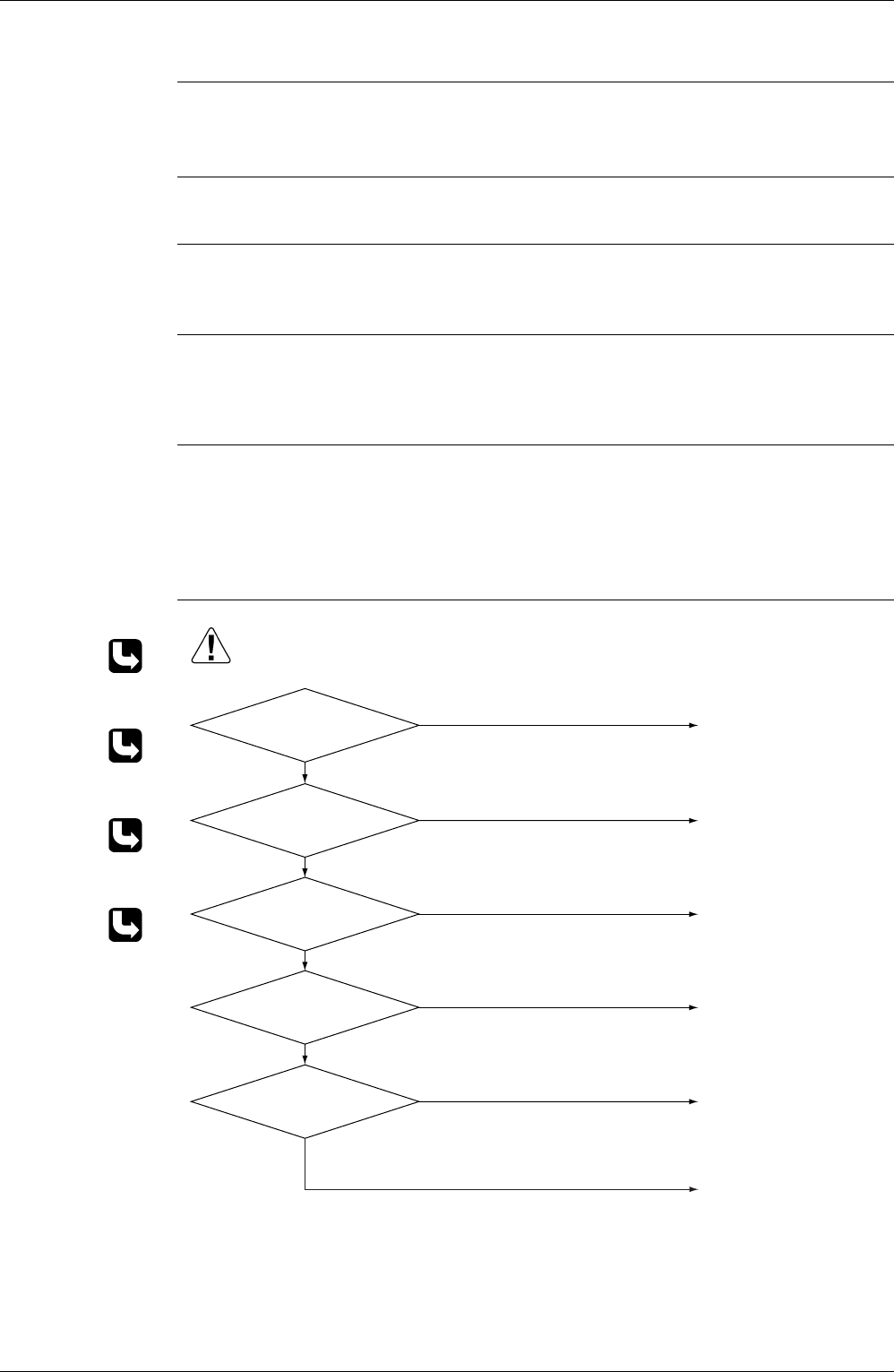
5.12 OL Activation (Compressor Overload)
Remote
Controller
Display
E5
Outdoor Unit LED
Display
A
5
1
4
2
1
3
4
4
1
Method of
Malfunction
Detection
A compressor overload is detected through compressor OL.
Malfunction
Decision
Conditions
If the compressor OL is activated twice, the system will be shut down.
The error counter will reset itself if this or any other error does not occur during the following
60-minute compressor running time (total time).
∗
The operating temperature condition is not specified.
Supposed
Causes
Refrigerant shortage
Four way valve malfunctioning
Outdoor unit PCB defective
Water mixed in the local piping
Electronic expansion valve defective
Stop valve defective
Troubleshooting
Check No.04
Refer to P.277
Check No.05
Refer to P.278
Check No.06
Refer to P.279
Check No.11
Refer to P.282
Insert the thermistor in
position.
Replace the discharge pipe
thermistor.
Replace the valve itself or
the coil.
Replace the four way valve
coil or the valve itself.
Replace the outdoor unit
PCB.
Refer to the refrigerant line
check procedure.
(R4697)
Caution
Be sure to turn off power switch before connect or disconnect connector,
or parts damage may be occurred.
Discharge pipe thermistor
disconnected?
YES
Malfunctioning
∗ Discharge pipe thermistor
NO
Functioning
Functioning
Check No. 11
Check the refrigerant line.
Malfunctioning
∗ Refrigerant shortage
∗ Water mixed
∗ Stop valve defective
Check No. 06
Check the thermistors
Malfunctioning
Functioning
Check No. 04
Check the electronic expantion
valve.
Malfunctioning
Functioning
Check No. 05
Check the four way valve.
Replace the outdoor unit
PCB.