
Specifications
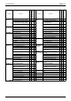
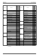
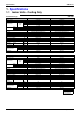
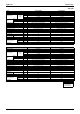

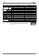
Table Of Contents
- Cover
- Table of Contents
- Part 1 List of Functions
- Part 2 Specifications
- Part 3 Printed Circuit Board Connector Wiring Diagram
- Part 4 Function and Control
- Part 5 Operation Manual
- Part 6 Service Diagnosis
- 1. Caution for Diagnosis
- 2. Problem Symptoms and Measures
- 3. Service Check Function
- 4. Code Indication on the Remote Controller
- 5. Troubleshooting
- 5.1 Indoor Units
- 5.2 Outdoor Units
- 5.3 Indoor Unit PCB Abnormality A1
- 5.4 Freeze-up Protection Control or High Pressure Control A5
- 5.5 Fan Motor or Related Abnormality A6
- 5.6 Thermistor or Related Abnormality (Indoor Unit) C4,C9
- 5.7 Front Panel Open / Close Fault C7
- 5.8 Signal Transmission Error (between Indoor and OutdoorUnit) U4
- 5.9 Unspecified Voltage (between Indoor and Outdoor Units) UA
- 5.10 Freeze-up Protection Control A5
- 5.11 Outdoor Unit PCB Abnormality E1
- 5.12 OL Activation (Compressor Overload) E5
- 5.13 Compressor Lock E6
- 5.14 DC Fan Lock E7
- 5.15 Input Over Current Detection E8
- 5.16 Discharge Pipe Temperature Control F3
- 5.17 High Pressure Control in Cooling F6
- 5.18 Compressor Sensor System Abnormality H0
- 5.19 Position Sensor Abnormality H6
- 5.20 CT or Related Abnormality H8
- 5.21 Thermistor or Related Abnormality (Outdoor Unit) P4,J3,J6,J8,J9,H9
- 5.22 Electrical Box Temperature Rise L3
- 5.23 Radiation Fin Temperature Rise L4
- 5.24 Output Over Current Detection L5
- 5.25 Insufficient Gas U0
- 5.26 Low-voltage Detection or Over-voltage Detection U2
- 5.27 Signal Transmission Error (on Outdoor Unit PCB) U7
- 5.28 Anti-icing Function in Other Rooms / UnspecifiedVoltage (between Indoor and Outdoor Units) UA,UH
- 6. Check
- Part 7 Removal Procedure
- Part 8 Others
- Part 9 Appendix
- Index
- Drawings & Flow Charts
SiBE12-713 Specifications
Specifications 15
50Hz 230V
Model FTKS35D3VMW FTKS35D3VML
Rated Capacity 3.5kW Class 3.5kW Class
Front Panel Color White Silver Line
Air Flow Rates
m³/min
(cfm)
H 8.9 (314) 8.9 (314)
M 6.9 (244) 6.9 (244)
L 4.8 (169) 4.8 (169)
SL 4.0 (141) 4.0 (141)
Fan
Type Cross Flow Fan Cross Flow Fan
Motor Output W 40 40
Speed Steps 5 Steps, Quiet, Auto 5 Steps, Quiet, Auto
Air Direction Control Right, Left, Horizontal, Downward Right, Left, Horizontal, Downward
Air Filter Removable-Washable-Mildew Proof Removable-Washable-Mildew Proof
Running Current (Rated) A 0.18 0.18
Power Consumption (Rated) W 40 40
Power Factor % 96.6 96.6
Temperature Control Microcomputer Control Microcomputer Control
Dimensions (H×W×D) mm 283×800×195 283×800×195
Packaged Dimensions (H×W×D) mm 265×855×340 265×855×340
Weight kg 9 9
Gross Weight kg 12 12
Operation
Sound
H/L/SL dBA 39/26/23 39/26/23
Sound Power H dBA 57 57
Heat Insulation Both Liquid and Gas Pipes Both Liquid and Gas Pipes
Piping Connection
Liquid mm
φ
6.4
φ
6.4
Gas mm
φ
9.5
φ
9.5
Drain mm
φ
18.0
φ
18.0
Drawing No. 3D051083 3D051084
Conversion Formulae
kcal/h=kW×860
Btu/h=kW×3414
cfm=m³/min×35.3
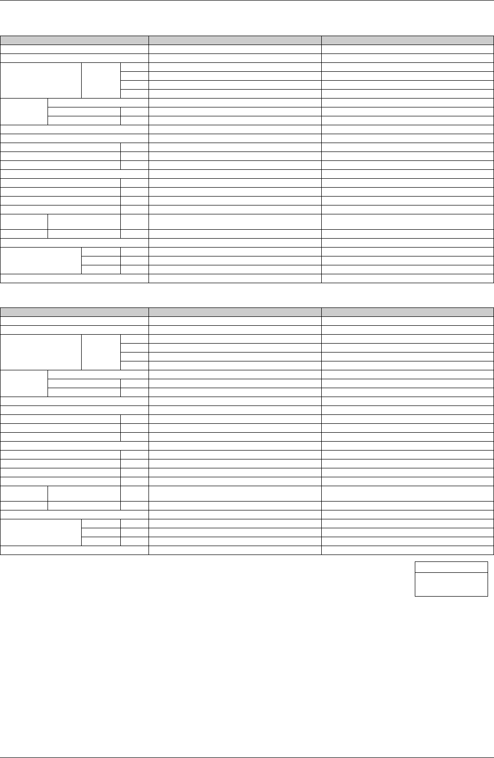
Model FTKS50D2V1W FTKS50D2V1L
Rated Capacity 5.0kW Class 5.0kW Class
Front Panel Color White Silver Line
Air Flow Rates
m³/min
(cfm)
H 11.4 (402) 11.4 (402)
M 9.3 (328) 9.3 (328)
L 7.1 (251) 7.1 (251)
SL 6.2 (219) 6.2 (219)
Fan
Type Cross Flow Fan Cross Flow Fan
Motor Output W 40 40
Speed Steps 5 Steps, Quiet, Auto 5 Steps, Quiet, Auto
Air Direction Control Right, Left, Horizontal, Downward Right, Left, Horizontal, Downward
Air Filter Removable-Washable-Mildew Proof Removable-Washable-Mildew Proof
Running Current (Rated) A 0.21 0.21
Power Consumption (Rated) W 48 48
Power Factor % 99.4 99.4
Temperature Control Microcomputer Control Microcomputer Control
Dimensions (H×W×D) mm 283×800×195 283×800×195
Packaged Dimensions (H×W×D) mm 265×855×340 265×855×340
Weight kg 9 9
Gross Weight kg 12 12
Operation
Sound
H/M/L/SL dBA 46/41/35/32 46/41/35/32
Sound Power H dBA 62 62
Heat Insulation Both Liquid and Gas Pipes Both Liquid and Gas Pipes
Piping Connection
Liquid mm
φ
6.4
φ
6.4
Gas mm
φ
12.7
φ
12.7
Drain mm
φ
18.0
φ
18.0
Drawing No. 3D051812 3D051813