
Specifications
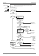
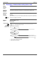
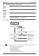
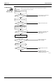
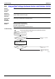
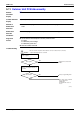
Table Of Contents
- Cover
- Table of Contents
- Part 1 List of Functions
- Part 2 Specifications
- Part 3 Printed Circuit Board Connector Wiring Diagram
- Part 4 Function and Control
- Part 5 Operation Manual
- Part 6 Service Diagnosis
- 1. Caution for Diagnosis
- 2. Problem Symptoms and Measures
- 3. Service Check Function
- 4. Code Indication on the Remote Controller
- 5. Troubleshooting
- 5.1 Indoor Units
- 5.2 Outdoor Units
- 5.3 Indoor Unit PCB Abnormality A1
- 5.4 Freeze-up Protection Control or High Pressure Control A5
- 5.5 Fan Motor or Related Abnormality A6
- 5.6 Thermistor or Related Abnormality (Indoor Unit) C4,C9
- 5.7 Front Panel Open / Close Fault C7
- 5.8 Signal Transmission Error (between Indoor and OutdoorUnit) U4
- 5.9 Unspecified Voltage (between Indoor and Outdoor Units) UA
- 5.10 Freeze-up Protection Control A5
- 5.11 Outdoor Unit PCB Abnormality E1
- 5.12 OL Activation (Compressor Overload) E5
- 5.13 Compressor Lock E6
- 5.14 DC Fan Lock E7
- 5.15 Input Over Current Detection E8
- 5.16 Discharge Pipe Temperature Control F3
- 5.17 High Pressure Control in Cooling F6
- 5.18 Compressor Sensor System Abnormality H0
- 5.19 Position Sensor Abnormality H6
- 5.20 CT or Related Abnormality H8
- 5.21 Thermistor or Related Abnormality (Outdoor Unit) P4,J3,J6,J8,J9,H9
- 5.22 Electrical Box Temperature Rise L3
- 5.23 Radiation Fin Temperature Rise L4
- 5.24 Output Over Current Detection L5
- 5.25 Insufficient Gas U0
- 5.26 Low-voltage Detection or Over-voltage Detection U2
- 5.27 Signal Transmission Error (on Outdoor Unit PCB) U7
- 5.28 Anti-icing Function in Other Rooms / UnspecifiedVoltage (between Indoor and Outdoor Units) UA,UH
- 6. Check
- Part 7 Removal Procedure
- Part 8 Others
- Part 9 Appendix
- Index
- Drawings & Flow Charts
SiBE12-713 Troubleshooting
Service Diagnosis 241
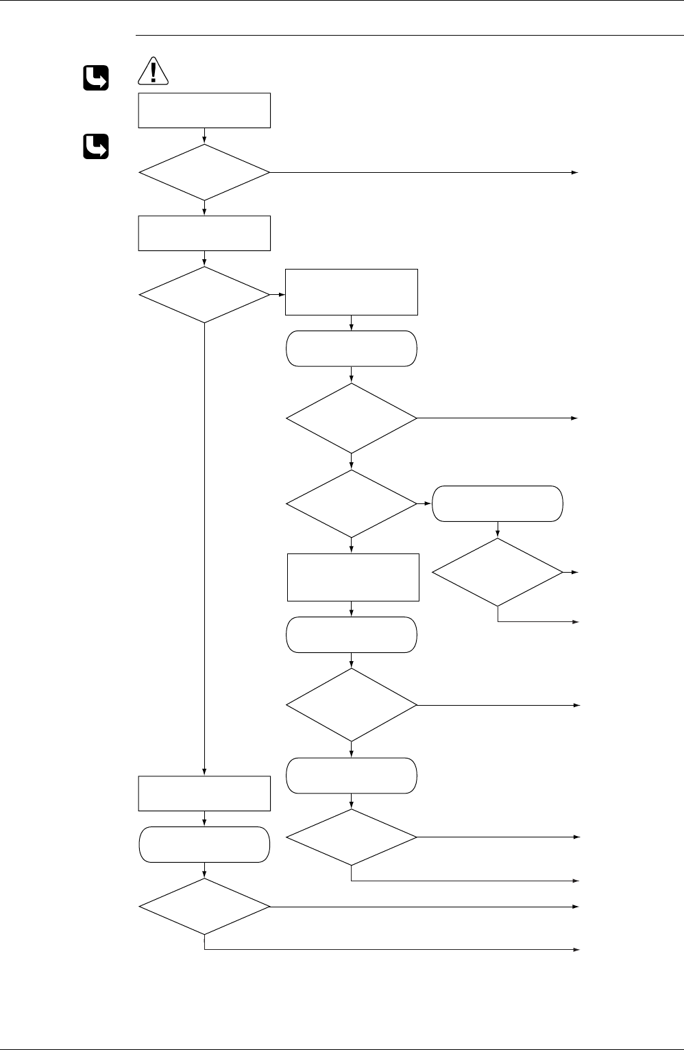
Troubleshooting
Check No.01
Refer to P.276
Check No.02
Refer to P.276
Replace fan motor.
Replace indoor
unit PCB (1) or (2).
Replace indoor
unit PCB (1) .
Replace indoor
unit PCB (2) .
Replace fan motor.
Note : Motor may
break when
the motor
connector is
disconnected
while
remaining
power supply.
Replace fan motor
and indoor PCB (2) .
Replace indoor
unit PCB (2) .
Replace fan motor.
Replace indoor
unit PCB (2) .
Turn off power supply
and rotate fan by hand.
Turn power ON and
operate fan.
Turn off power supply
and disconnect fan motor
connector, then turn
power ON.
Check No.01
Check output of fan
motor connector
Is motor
power voltage
DC 200V
generated?
Is motor
control power voltage
DC 15V
generated?
Turn off power supply and
disconnect fan motor
connector, then turn
power ON again.
Does it rotate?
Stop fan motor.
Is rotation
number command pulse
generated?
Is rotation
number command pulse
generated?
Check No.01
Check output of fan
motor connector
Check No.01
Check output of fan
motor connector
Check No.01
Check output of fan
motor connector
Check No.02
Check output of indoor
unit PCB (1)
Is motor control
power voltage DC 16V
generetad?
Is rotation
number command
voltage DC 5V
generated?
Does fan rotate
smoothly?
(R6961)
YES
YES
NO
YES
YES
NO
YES
NO
NO
YES
NO
YES
NO
YES
NO
NO
Caution
Be sure to turn off power switch before connect or disconnect connector,
or parts damage may be occurred.