
Specifications
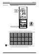
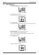
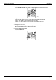
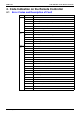
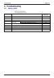
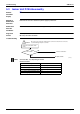
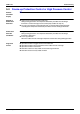
Table Of Contents
- Cover
- Table of Contents
- Part 1 List of Functions
- Part 2 Specifications
- Part 3 Printed Circuit Board Connector Wiring Diagram
- Part 4 Function and Control
- Part 5 Operation Manual
- Part 6 Service Diagnosis
- 1. Caution for Diagnosis
- 2. Problem Symptoms and Measures
- 3. Service Check Function
- 4. Code Indication on the Remote Controller
- 5. Troubleshooting
- 5.1 Indoor Units
- 5.2 Outdoor Units
- 5.3 Indoor Unit PCB Abnormality A1
- 5.4 Freeze-up Protection Control or High Pressure Control A5
- 5.5 Fan Motor or Related Abnormality A6
- 5.6 Thermistor or Related Abnormality (Indoor Unit) C4,C9
- 5.7 Front Panel Open / Close Fault C7
- 5.8 Signal Transmission Error (between Indoor and OutdoorUnit) U4
- 5.9 Unspecified Voltage (between Indoor and Outdoor Units) UA
- 5.10 Freeze-up Protection Control A5
- 5.11 Outdoor Unit PCB Abnormality E1
- 5.12 OL Activation (Compressor Overload) E5
- 5.13 Compressor Lock E6
- 5.14 DC Fan Lock E7
- 5.15 Input Over Current Detection E8
- 5.16 Discharge Pipe Temperature Control F3
- 5.17 High Pressure Control in Cooling F6
- 5.18 Compressor Sensor System Abnormality H0
- 5.19 Position Sensor Abnormality H6
- 5.20 CT or Related Abnormality H8
- 5.21 Thermistor or Related Abnormality (Outdoor Unit) P4,J3,J6,J8,J9,H9
- 5.22 Electrical Box Temperature Rise L3
- 5.23 Radiation Fin Temperature Rise L4
- 5.24 Output Over Current Detection L5
- 5.25 Insufficient Gas U0
- 5.26 Low-voltage Detection or Over-voltage Detection U2
- 5.27 Signal Transmission Error (on Outdoor Unit PCB) U7
- 5.28 Anti-icing Function in Other Rooms / UnspecifiedVoltage (between Indoor and Outdoor Units) UA,UH
- 6. Check
- Part 7 Removal Procedure
- Part 8 Others
- Part 9 Appendix
- Index
- Drawings & Flow Charts
SiBE12-713 Troubleshooting
Service Diagnosis 239
5.5 Fan Motor or Related Abnormality
5.5.1 AC Motor
Remote
Controller
Display
A6
Method of
Malfunction
Detection
The rotation speed detected by the Hall IC during fan motor operation is used to determine
abnormal fan motor operation.
Malfunction
Decision
Conditions
When the detected rotation speed does not reach the demanded rotation speed of the target
tap, and is less than 50% of the maximum fan motor rotation speed.
Supposed
Causes
Operation halt due to short circuit inside the fan motor winding.
Operation halt due to breaking of wire inside the fan motor.
Operation halt due to breaking of the fan motor lead wires.
Operation halt due to faulty capacitor of the fan motor.
Detection error due to faulty control PCB.
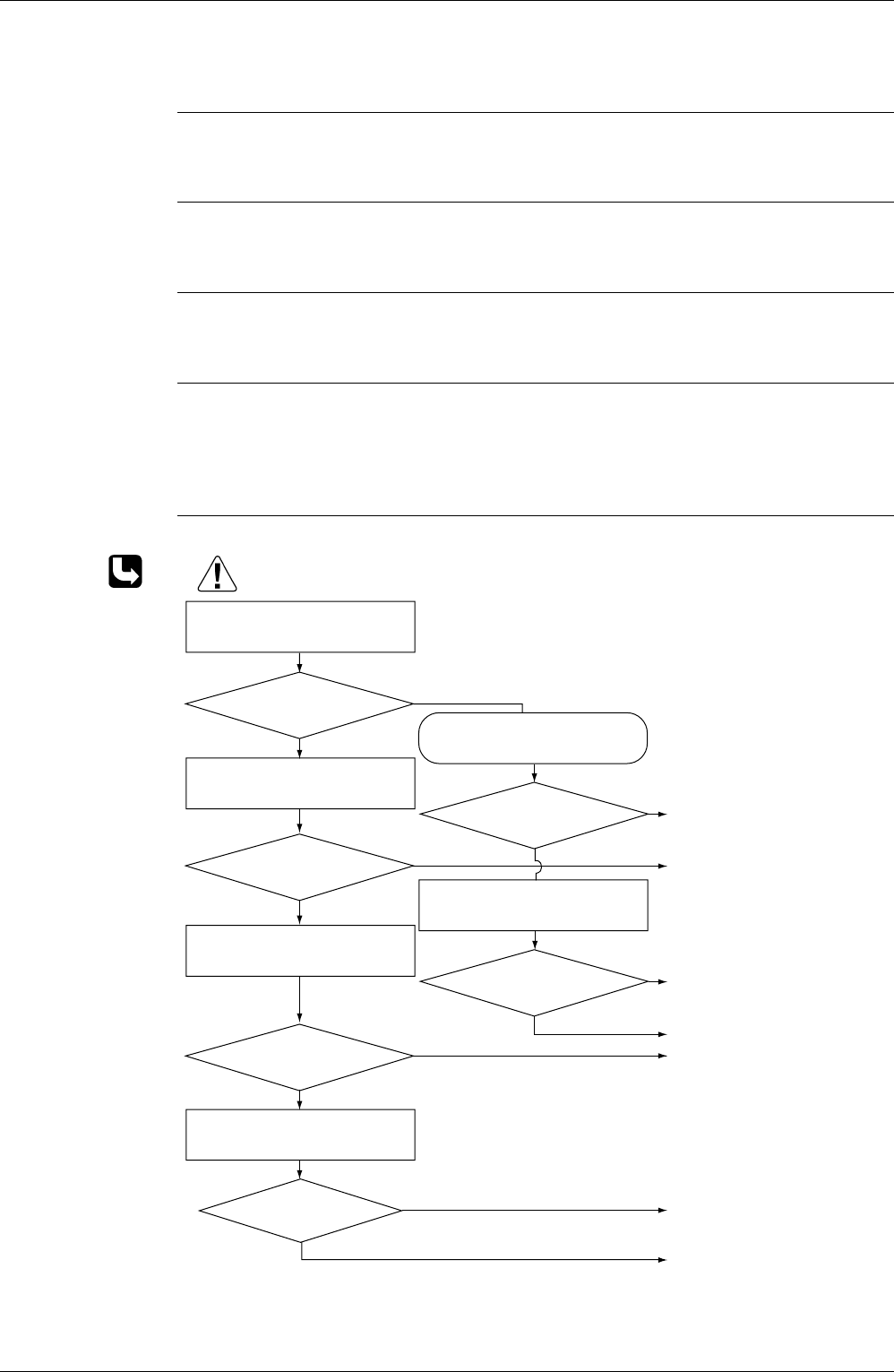
Troubleshooting
Check No.16
Refer to P.285
Rotate the fan by hand.
Check No. 16
Check Hall IC
Operate the fan.
Does it rotate?
NO
Does it rotate smoothly?
Is there an output?
Is it at the rated voltage?
∗
Is there conductivity?
NO
Check the capacitor's
conductivity
Check the fan motor voltage.
(immediately after re-start)
Is it at the rated voltage?
∗
Check the fan motor voltage.
NO
NO
NO
NO
YES
YES
YES
YES
YES
YES
Replace the fan motor or control
PCB.
Replace the fan motor
Replace control PCB.
Replace the fan motor.
Replace the control PCB.
∗ Measure the voltage between
the red and black lead wires of
the fan motor, and check if the
maximum voltage reaches the
rated voltage.
Replace the capacitor.
(Replace the control PCB.)
Replace the fan motor.
(R3219)
Caution
Be sure to turn off power switch before connect or disconnect connector,
or parts damage may be occurred.