
Specifications
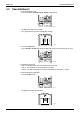
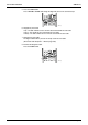
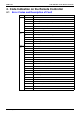
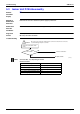
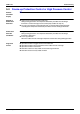
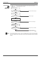
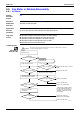
Table Of Contents
- Cover
- Table of Contents
- Part 1 List of Functions
- Part 2 Specifications
- Part 3 Printed Circuit Board Connector Wiring Diagram
- Part 4 Function and Control
- Part 5 Operation Manual
- Part 6 Service Diagnosis
- 1. Caution for Diagnosis
- 2. Problem Symptoms and Measures
- 3. Service Check Function
- 4. Code Indication on the Remote Controller
- 5. Troubleshooting
- 5.1 Indoor Units
- 5.2 Outdoor Units
- 5.3 Indoor Unit PCB Abnormality A1
- 5.4 Freeze-up Protection Control or High Pressure Control A5
- 5.5 Fan Motor or Related Abnormality A6
- 5.6 Thermistor or Related Abnormality (Indoor Unit) C4,C9
- 5.7 Front Panel Open / Close Fault C7
- 5.8 Signal Transmission Error (between Indoor and OutdoorUnit) U4
- 5.9 Unspecified Voltage (between Indoor and Outdoor Units) UA
- 5.10 Freeze-up Protection Control A5
- 5.11 Outdoor Unit PCB Abnormality E1
- 5.12 OL Activation (Compressor Overload) E5
- 5.13 Compressor Lock E6
- 5.14 DC Fan Lock E7
- 5.15 Input Over Current Detection E8
- 5.16 Discharge Pipe Temperature Control F3
- 5.17 High Pressure Control in Cooling F6
- 5.18 Compressor Sensor System Abnormality H0
- 5.19 Position Sensor Abnormality H6
- 5.20 CT or Related Abnormality H8
- 5.21 Thermistor or Related Abnormality (Outdoor Unit) P4,J3,J6,J8,J9,H9
- 5.22 Electrical Box Temperature Rise L3
- 5.23 Radiation Fin Temperature Rise L4
- 5.24 Output Over Current Detection L5
- 5.25 Insufficient Gas U0
- 5.26 Low-voltage Detection or Over-voltage Detection U2
- 5.27 Signal Transmission Error (on Outdoor Unit PCB) U7
- 5.28 Anti-icing Function in Other Rooms / UnspecifiedVoltage (between Indoor and Outdoor Units) UA,UH
- 6. Check
- Part 7 Removal Procedure
- Part 8 Others
- Part 9 Appendix
- Index
- Drawings & Flow Charts
Troubleshooting SiBE12-713
236 Service Diagnosis
5.3 Indoor Unit PCB Abnormality
Remote
Controller
Display
A1
Method of
Malfunction
Detection
Evaluation of zero-cross detection of power supply by indoor unit.
Malfunction
Decision
Conditions
When there is no zero-cross detection in approximately 10 continuous seconds.
Supposed
Causes
Faulty indoor unit PCB
Faulty connector connection
Troubleshooting
Note: Connector Nos. vary depending on models.
Control connector
Connector connection check
(note).
YES
Is it normal?
NO
Correct connections.
Replace PCBs.
(R1400)
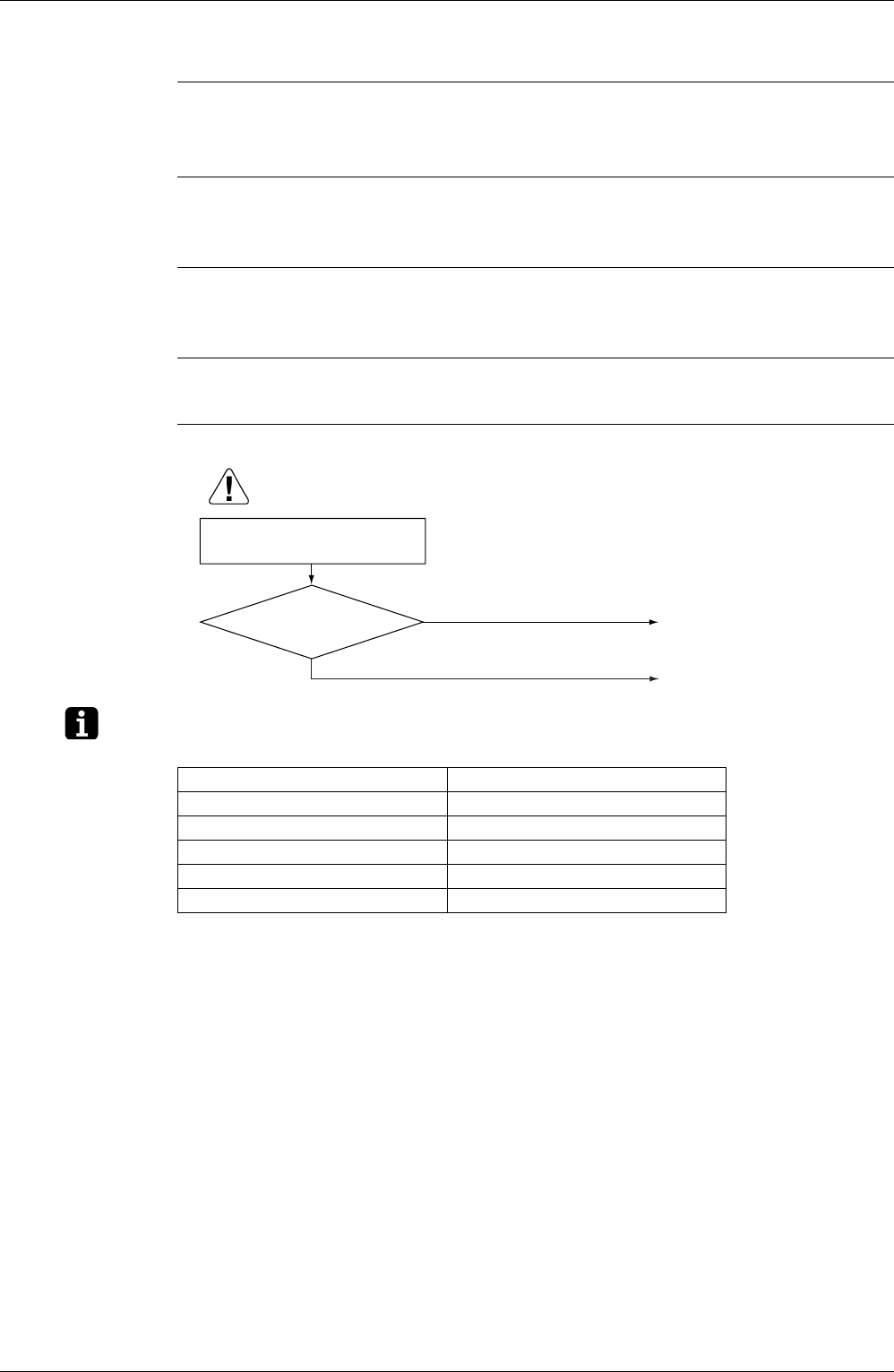
Caution
Be sure to turn off power switch before connect or disconnect connector,
or parts damage may be occurred.
Model Type Connector No.
Wall Mounted Type 20 / 25 / 35 class Terminal strip~Control PCB
Wall Mounted Type 50 / 60 / 71 class Terminal strip~Control PCB
Duct Connected Type Terminal strip~Control PCB
Floor / Ceiling Suspended Dual Type S37
Floor Standing Type Terminal strip~Control PCB