
Specifications
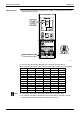
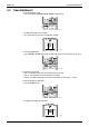
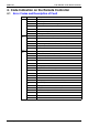
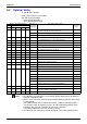
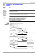
Table Of Contents
- Cover
- Table of Contents
- Part 1 List of Functions
- Part 2 Specifications
- Part 3 Printed Circuit Board Connector Wiring Diagram
- Part 4 Function and Control
- Part 5 Operation Manual
- Part 6 Service Diagnosis
- 1. Caution for Diagnosis
- 2. Problem Symptoms and Measures
- 3. Service Check Function
- 4. Code Indication on the Remote Controller
- 5. Troubleshooting
- 5.1 Indoor Units
- 5.2 Outdoor Units
- 5.3 Indoor Unit PCB Abnormality A1
- 5.4 Freeze-up Protection Control or High Pressure Control A5
- 5.5 Fan Motor or Related Abnormality A6
- 5.6 Thermistor or Related Abnormality (Indoor Unit) C4,C9
- 5.7 Front Panel Open / Close Fault C7
- 5.8 Signal Transmission Error (between Indoor and OutdoorUnit) U4
- 5.9 Unspecified Voltage (between Indoor and Outdoor Units) UA
- 5.10 Freeze-up Protection Control A5
- 5.11 Outdoor Unit PCB Abnormality E1
- 5.12 OL Activation (Compressor Overload) E5
- 5.13 Compressor Lock E6
- 5.14 DC Fan Lock E7
- 5.15 Input Over Current Detection E8
- 5.16 Discharge Pipe Temperature Control F3
- 5.17 High Pressure Control in Cooling F6
- 5.18 Compressor Sensor System Abnormality H0
- 5.19 Position Sensor Abnormality H6
- 5.20 CT or Related Abnormality H8
- 5.21 Thermistor or Related Abnormality (Outdoor Unit) P4,J3,J6,J8,J9,H9
- 5.22 Electrical Box Temperature Rise L3
- 5.23 Radiation Fin Temperature Rise L4
- 5.24 Output Over Current Detection L5
- 5.25 Insufficient Gas U0
- 5.26 Low-voltage Detection or Over-voltage Detection U2
- 5.27 Signal Transmission Error (on Outdoor Unit PCB) U7
- 5.28 Anti-icing Function in Other Rooms / UnspecifiedVoltage (between Indoor and Outdoor Units) UA,UH
- 6. Check
- Part 7 Removal Procedure
- Part 8 Others
- Part 9 Appendix
- Index
- Drawings & Flow Charts
SiBE12-713 Troubleshooting
Service Diagnosis 235
5.2 Outdoor Units
4
: ON,
1
: OFF,
5
: Blinks
Green : Flashes when in normal condition
Red : OFF in normal condition
- : Not used for troubleshooting
∗
: Varies depending on the cases.
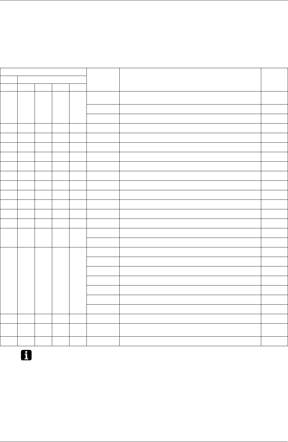
Note: 1. The indications in the parenthesis ( ) in the remote controller display column are displayed
only when system-down occurs.
2. When a sensor error occurs, check the remote controller display to determine which sensor
is malfunctioning.
If the remote controller does not indicate the error type, conduct the following operation.
*Turn the power switch off and back on again. If the same LED indication appears again
immediately after the power is turned on, the fault is in the thermistor.
*If the above condition does not result, the fault is in the CT.
3. The indoor unit error indication may take the precedence in the remote controller display.
Outdoor Unit LED Indication Indication on
the remote
controller
Description of The Fault
Reference
Page
Green Red
A1234
5333300
Outdoor unit in normal condition
(Conduct a diagnosis of the indoor unit.)
—
UA
Unspecified voltage (between indoor and outdoor units)
275
UH
Anti-icing function in other rooms
275
53344 (U0)
Insufficient gas
271
54334U2
Low-voltage detection or over-voltage detection
273
53444U7
Signal transmission error (on outdoor unit PCB)
274
54344A5
Freeze-up protection control
247
54443E1
Outdoor unit PCB abnormality
249
54343 (E5)
OL activation (compressor overload)
250
53443 (E6)
Compressor lock
251
54444E7
DC fan lock
252
53434E8
Input over current detection
253
54343F3
Discharge pipe temperature control
255
54344F6
High pressure control in cooling
256
54433H0
Compressor sensor system abnormality
258
H8
CT or related abnormality
261
54433H6
Position sensor abnormality
260
H9
Outdoor air thermistor or related abnormality
263
J3
Discharge pipe thermistor or related abnormality
263
J6
Heat exchanger thermistor or related abnormality
263
J8
Liquid pipe thermistor or related abnormality
263
J9
Gas pipe thermistor or related abnormality
263
P4
Radiation fin thermistor or related abnormality
263
54434L3
Electrical box temperature rise
265
53334L4
Radiation fin temperature rise
(Protection of driver overheating)
267
53343L5
Output over current detection
269