
Specifications
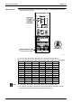
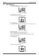
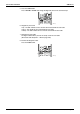
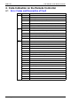
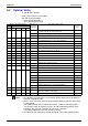
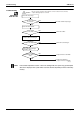
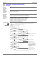
Table Of Contents
- Cover
- Table of Contents
- Part 1 List of Functions
- Part 2 Specifications
- Part 3 Printed Circuit Board Connector Wiring Diagram
- Part 4 Function and Control
- Part 5 Operation Manual
- Part 6 Service Diagnosis
- 1. Caution for Diagnosis
- 2. Problem Symptoms and Measures
- 3. Service Check Function
- 4. Code Indication on the Remote Controller
- 5. Troubleshooting
- 5.1 Indoor Units
- 5.2 Outdoor Units
- 5.3 Indoor Unit PCB Abnormality A1
- 5.4 Freeze-up Protection Control or High Pressure Control A5
- 5.5 Fan Motor or Related Abnormality A6
- 5.6 Thermistor or Related Abnormality (Indoor Unit) C4,C9
- 5.7 Front Panel Open / Close Fault C7
- 5.8 Signal Transmission Error (between Indoor and OutdoorUnit) U4
- 5.9 Unspecified Voltage (between Indoor and Outdoor Units) UA
- 5.10 Freeze-up Protection Control A5
- 5.11 Outdoor Unit PCB Abnormality E1
- 5.12 OL Activation (Compressor Overload) E5
- 5.13 Compressor Lock E6
- 5.14 DC Fan Lock E7
- 5.15 Input Over Current Detection E8
- 5.16 Discharge Pipe Temperature Control F3
- 5.17 High Pressure Control in Cooling F6
- 5.18 Compressor Sensor System Abnormality H0
- 5.19 Position Sensor Abnormality H6
- 5.20 CT or Related Abnormality H8
- 5.21 Thermistor or Related Abnormality (Outdoor Unit) P4,J3,J6,J8,J9,H9
- 5.22 Electrical Box Temperature Rise L3
- 5.23 Radiation Fin Temperature Rise L4
- 5.24 Output Over Current Detection L5
- 5.25 Insufficient Gas U0
- 5.26 Low-voltage Detection or Over-voltage Detection U2
- 5.27 Signal Transmission Error (on Outdoor Unit PCB) U7
- 5.28 Anti-icing Function in Other Rooms / UnspecifiedVoltage (between Indoor and Outdoor Units) UA,UH
- 6. Check
- Part 7 Removal Procedure
- Part 8 Others
- Part 9 Appendix
- Index
- Drawings & Flow Charts
SiBE12-713 Code Indication on the Remote Controller
Service Diagnosis 233
4. Code Indication on the Remote Controller
4.1 Error Codes and Description of Fault
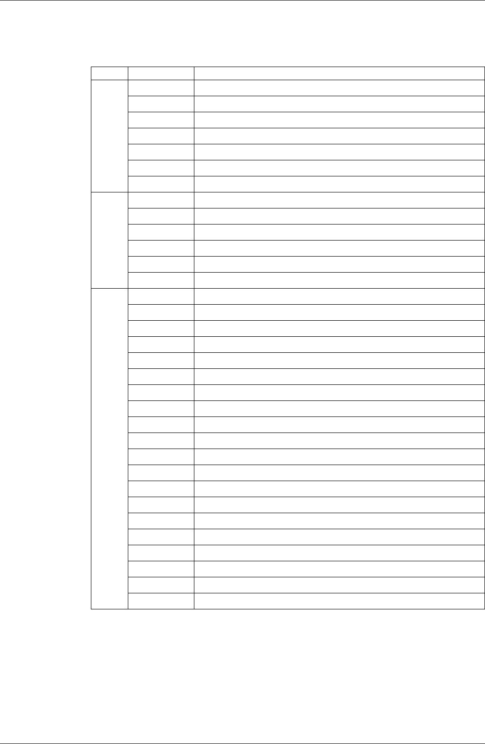
Code Indication Description of Problem
System
00
Normal
U0
Insufficient gas
U2
Low-voltage detection or over-voltage detection
U4
Signal transmission error (between indoor and outdoor units)
U7
Signal transmission error (on outdoor unit PCB)
UA
Unspecified voltage (between indoor and outdoor units)
UH
Anti-icing function in other rooms
Indoor
Unit
A1
Indoor unit PCB abnormality
A5
Freeze-up protection function or high pressure control
A6
Fan motor or related abnormality
C4
Heat exchanger temperature thermistor abnormality
C7
Front panel open / close fault
C9
Room temperature thermistor abnormality
Outdoor
Unit
A5
Freeze-up protection control
E1
Outdoor unit PCB abnormality
E5
OL activation (compressor overloaded)
E6
Compressor lock
E7
DC fan lock
E8
Input over current detection
F3
Discharge pipe temperature control
F6
High pressure control in cooling
H0
Compressor sensor system abnormality
H6
Position sensor abnormality
H8
CT or related abnormality
H9
Outdoor air thermistor or related abnormality
J3
Discharge pipe thermistor or related abnormality
J6
Heat exchanger thermistor or related abnormality
J8
Liquid pipe thermistor or related abnormality
J9
Gas pipe thermistor or related abnormality
L3
Electrical box temperature rise
L4
Radiation fin temperature rise
L5
Output over current detection
P4
Radiation fin thermistor or related abnormality