
Specifications
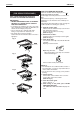
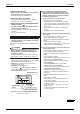
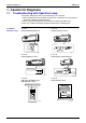
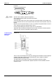
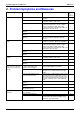
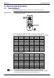
Table Of Contents
- Cover
- Table of Contents
- Part 1 List of Functions
- Part 2 Specifications
- Part 3 Printed Circuit Board Connector Wiring Diagram
- Part 4 Function and Control
- Part 5 Operation Manual
- Part 6 Service Diagnosis
- 1. Caution for Diagnosis
- 2. Problem Symptoms and Measures
- 3. Service Check Function
- 4. Code Indication on the Remote Controller
- 5. Troubleshooting
- 5.1 Indoor Units
- 5.2 Outdoor Units
- 5.3 Indoor Unit PCB Abnormality A1
- 5.4 Freeze-up Protection Control or High Pressure Control A5
- 5.5 Fan Motor or Related Abnormality A6
- 5.6 Thermistor or Related Abnormality (Indoor Unit) C4,C9
- 5.7 Front Panel Open / Close Fault C7
- 5.8 Signal Transmission Error (between Indoor and OutdoorUnit) U4
- 5.9 Unspecified Voltage (between Indoor and Outdoor Units) UA
- 5.10 Freeze-up Protection Control A5
- 5.11 Outdoor Unit PCB Abnormality E1
- 5.12 OL Activation (Compressor Overload) E5
- 5.13 Compressor Lock E6
- 5.14 DC Fan Lock E7
- 5.15 Input Over Current Detection E8
- 5.16 Discharge Pipe Temperature Control F3
- 5.17 High Pressure Control in Cooling F6
- 5.18 Compressor Sensor System Abnormality H0
- 5.19 Position Sensor Abnormality H6
- 5.20 CT or Related Abnormality H8
- 5.21 Thermistor or Related Abnormality (Outdoor Unit) P4,J3,J6,J8,J9,H9
- 5.22 Electrical Box Temperature Rise L3
- 5.23 Radiation Fin Temperature Rise L4
- 5.24 Output Over Current Detection L5
- 5.25 Insufficient Gas U0
- 5.26 Low-voltage Detection or Over-voltage Detection U2
- 5.27 Signal Transmission Error (on Outdoor Unit PCB) U7
- 5.28 Anti-icing Function in Other Rooms / UnspecifiedVoltage (between Indoor and Outdoor Units) UA,UH
- 6. Check
- Part 7 Removal Procedure
- Part 8 Others
- Part 9 Appendix
- Index
- Drawings & Flow Charts
SiBE12-713 Service Check Function
Service Diagnosis 229
3. Service Check Function
3.1 Check Method 1
The temperature display sections on the main unit indicate corresponding codes.
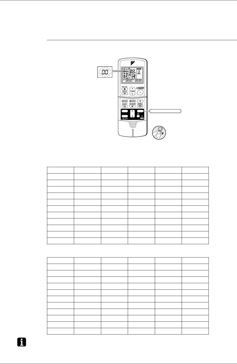
ARC433 Series 1. When the timer cancel button is held down for 5 seconds, a “00” indication flashes on the
temperature display section.
2. Press the timer cancel button repeatedly until a continuous beep is produced.
The code indication changes in the sequence shown below, and notifies with a long beep.
<In case of ARC433B70, 71>
Note: 1. A short beep and two consecutive beeps indicate non-corresponding codes.
2. To cancel the code display, hold the timer cancel button down for 5 seconds. The code
display also cancels itself if the button is not pressed for 1 minute.
No. Code No. Code No. Code
1 00 12 C7 23 H0
2 U4 13 H8 24 E1
3 F3 14 J3 25 P4
4 E6 15 A3 26 L3
5 L5 16 A1 27 L4
6 A6 17 C4 28 H6
7 E5 18 C5 29 H7
8 F6 19 H9 30 U2
9 C9 20 J6 31 UH
10 U0 21 UA 32 EA
11 E7 22 A5 33 AH
<
ARC433B70, 71
>
(R6849)
TIMER
ON
CANCEL
OFF
TIMER CANCEL button
It cancels the timer setting.
No. Code No. Code No. Code
1 00 12 F6 23 A1
2 U4 13 C7 24 E1
3 L5 14 A3 25 UA
4 E6 15 H8 26 UH
5 H6 16 H9 27 P4
6 H0 17 C9 28 L3
7 A6 18 C4 29 L4
8 E7 19 C5 30 H7
9 U0 20 J3 31 U2
10 F3 21 J6 32 EA
11 A5 22 E5 33 AH