
Specifications
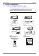
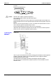
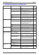
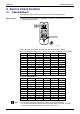
Table Of Contents
- Cover
- Table of Contents
- Part 1 List of Functions
- Part 2 Specifications
- Part 3 Printed Circuit Board Connector Wiring Diagram
- Part 4 Function and Control
- Part 5 Operation Manual
- Part 6 Service Diagnosis
- 1. Caution for Diagnosis
- 2. Problem Symptoms and Measures
- 3. Service Check Function
- 4. Code Indication on the Remote Controller
- 5. Troubleshooting
- 5.1 Indoor Units
- 5.2 Outdoor Units
- 5.3 Indoor Unit PCB Abnormality A1
- 5.4 Freeze-up Protection Control or High Pressure Control A5
- 5.5 Fan Motor or Related Abnormality A6
- 5.6 Thermistor or Related Abnormality (Indoor Unit) C4,C9
- 5.7 Front Panel Open / Close Fault C7
- 5.8 Signal Transmission Error (between Indoor and OutdoorUnit) U4
- 5.9 Unspecified Voltage (between Indoor and Outdoor Units) UA
- 5.10 Freeze-up Protection Control A5
- 5.11 Outdoor Unit PCB Abnormality E1
- 5.12 OL Activation (Compressor Overload) E5
- 5.13 Compressor Lock E6
- 5.14 DC Fan Lock E7
- 5.15 Input Over Current Detection E8
- 5.16 Discharge Pipe Temperature Control F3
- 5.17 High Pressure Control in Cooling F6
- 5.18 Compressor Sensor System Abnormality H0
- 5.19 Position Sensor Abnormality H6
- 5.20 CT or Related Abnormality H8
- 5.21 Thermistor or Related Abnormality (Outdoor Unit) P4,J3,J6,J8,J9,H9
- 5.22 Electrical Box Temperature Rise L3
- 5.23 Radiation Fin Temperature Rise L4
- 5.24 Output Over Current Detection L5
- 5.25 Insufficient Gas U0
- 5.26 Low-voltage Detection or Over-voltage Detection U2
- 5.27 Signal Transmission Error (on Outdoor Unit PCB) U7
- 5.28 Anti-icing Function in Other Rooms / UnspecifiedVoltage (between Indoor and Outdoor Units) UA,UH
- 6. Check
- Part 7 Removal Procedure
- Part 8 Others
- Part 9 Appendix
- Index
- Drawings & Flow Charts
Problem Symptoms and Measures SiBE12-713
228 Service Diagnosis
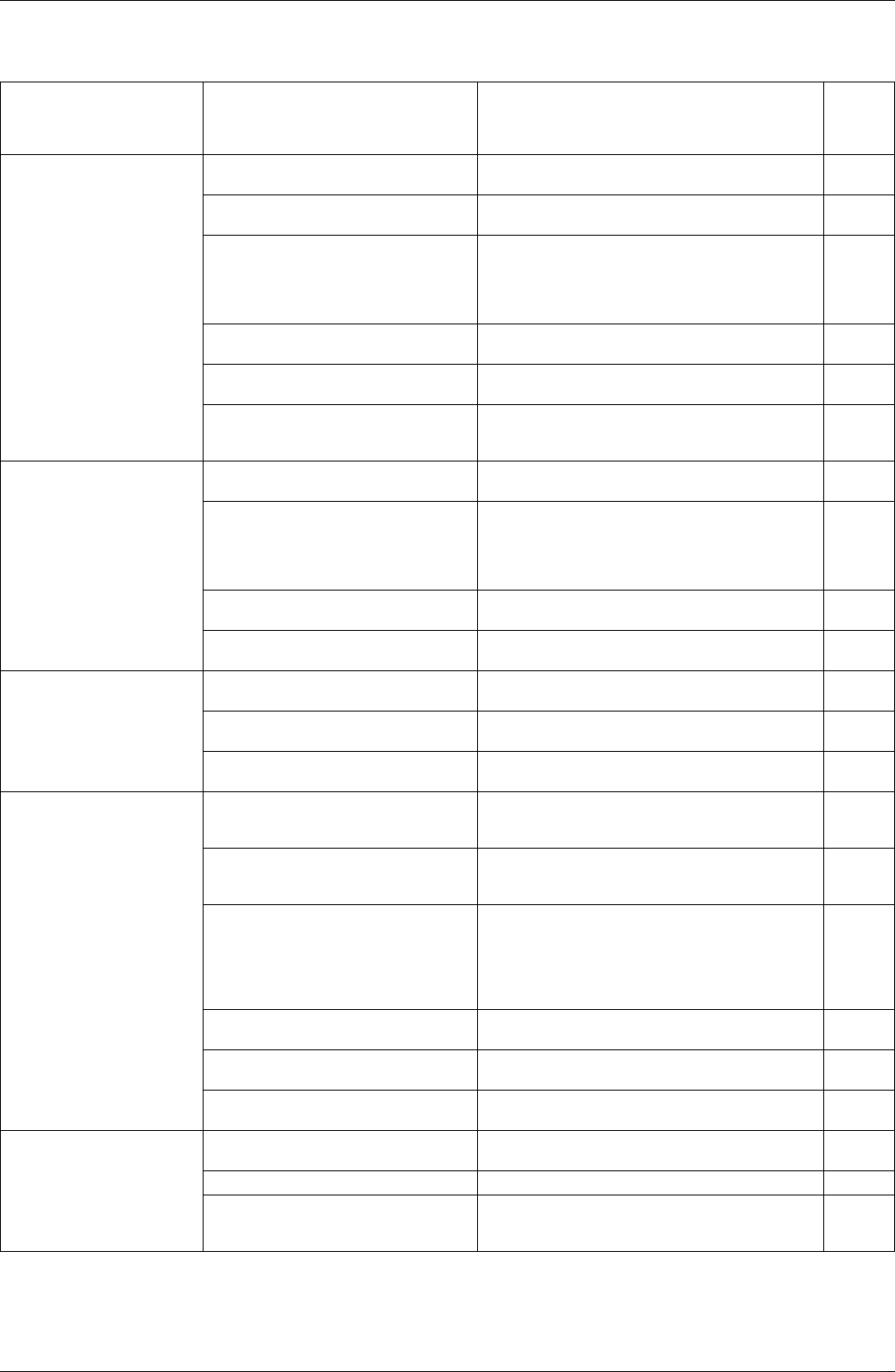
2. Problem Symptoms and Measures
Problem Symptom Check Item Details of Measure Page
No.
to be
referred
None of the units operates. Check the power supply. Check to make sure that the rated voltage is
supplied.
—
Check the type of the indoor units. Check to make sure that the indoor unit type is
compatible with the outdoor unit.
—
Check the outdoor air temperature. Heating operation cannot be used when the
outdoor air temperature is 15.5°C or higher
(only for heat pump model), and cooling
operation cannot be used when the outdoor air
temperature is below –10 °C
—
Diagnosis with indoor unit LED
indication
— 234
Diagnosis with outdoor unit LED
indication
— 235
Check the remote controller
addresses.
Check to make sure that address settings for
the remote controller and indoor unit are
correct.
—
Operation sometimes
stops.
Check the power supply. A power failure of 2 to 10 cycles can stop air
conditioner operation. (Operation lamp OFF)
—
Check the outdoor air temperature. Heating operation cannot be used when the
outdoor air temperature is 15.5°C or higher
(only for heat pump model), and cooling
operation cannot be used when the outdoor air
temperature is below –10°C
—
Diagnosis with indoor unit LED
indication
— 234
Diagnosis with outdoor unit LED
indication
— 235
Some indoor units do not
operate.
Check the type of the indoor units. Check to make sure that the indoor unit type is
compatible with the outdoor unit.
—
Diagnosis with indoor unit LED
indication
— 234
Diagnosis with outdoor unit LED
indication
— 235
Equipment operates but
does not cool, or does not
heat (only for heat pump
model).
Check for wiring and piping errors in
the indoor and outdoor units
connection wires and pipes.
Conduct the wiring/piping error check described
on the product diagnosis nameplate.
—
Check for thermistor detection errors. Check to make sure that the main unit’s
thermistor has not dismounted from the pipe
holder.
—
Check for faulty operation of the
electronic expansion valve.
Set the units to cooling operation, and compare
the temperatures of the liquid side connection
pipes of the connection section among rooms to
check the opening and closing operation of the
electronic expansion valves of the individual
units.
—
Diagnosis with indoor unit LED
indication
— 234
Diagnosis with outdoor unit LED
indication
— 235
Diagnosis by service port pressure
and operating current
Check for insufficient gas. 282
Large operating noise and
vibrations
Check the output voltage of the
power transistor.
— 283
Check the power transistor. — —
Check the installation condition. Check to make sure that the required spaces
for installation (specified in the Engineering
Data book, etc.) are provided.
—