
Specifications
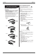

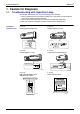
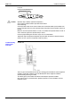
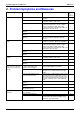
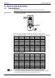
Table Of Contents
- Cover
- Table of Contents
- Part 1 List of Functions
- Part 2 Specifications
- Part 3 Printed Circuit Board Connector Wiring Diagram
- Part 4 Function and Control
- Part 5 Operation Manual
- Part 6 Service Diagnosis
- 1. Caution for Diagnosis
- 2. Problem Symptoms and Measures
- 3. Service Check Function
- 4. Code Indication on the Remote Controller
- 5. Troubleshooting
- 5.1 Indoor Units
- 5.2 Outdoor Units
- 5.3 Indoor Unit PCB Abnormality A1
- 5.4 Freeze-up Protection Control or High Pressure Control A5
- 5.5 Fan Motor or Related Abnormality A6
- 5.6 Thermistor or Related Abnormality (Indoor Unit) C4,C9
- 5.7 Front Panel Open / Close Fault C7
- 5.8 Signal Transmission Error (between Indoor and OutdoorUnit) U4
- 5.9 Unspecified Voltage (between Indoor and Outdoor Units) UA
- 5.10 Freeze-up Protection Control A5
- 5.11 Outdoor Unit PCB Abnormality E1
- 5.12 OL Activation (Compressor Overload) E5
- 5.13 Compressor Lock E6
- 5.14 DC Fan Lock E7
- 5.15 Input Over Current Detection E8
- 5.16 Discharge Pipe Temperature Control F3
- 5.17 High Pressure Control in Cooling F6
- 5.18 Compressor Sensor System Abnormality H0
- 5.19 Position Sensor Abnormality H6
- 5.20 CT or Related Abnormality H8
- 5.21 Thermistor or Related Abnormality (Outdoor Unit) P4,J3,J6,J8,J9,H9
- 5.22 Electrical Box Temperature Rise L3
- 5.23 Radiation Fin Temperature Rise L4
- 5.24 Output Over Current Detection L5
- 5.25 Insufficient Gas U0
- 5.26 Low-voltage Detection or Over-voltage Detection U2
- 5.27 Signal Transmission Error (on Outdoor Unit PCB) U7
- 5.28 Anti-icing Function in Other Rooms / UnspecifiedVoltage (between Indoor and Outdoor Units) UA,UH
- 6. Check
- Part 7 Removal Procedure
- Part 8 Others
- Part 9 Appendix
- Index
- Drawings & Flow Charts
SiBE12-713 Caution for Diagnosis
Service Diagnosis 227
In case of
FLK(X)S 25/35/50/60 B Series
Caution: Operation stops suddenly. (Operation lamp blinks.)
Cause of above trouble could be "Operation mode conflict".
Check followings;
Are the operation modes all the same for indoor units connected to Multi system outdoor unit?
If not set all indoor units to the same operation mode and confirm that the operation lamp is not
blinking.
Moreover, when the operation mode is in "Auto", set all indoor unit operation mode to "Cool" or
"Heat" and check again if the operation lamp is normal.
If the lamp stops blinking after the above steps, there is no malfunction.
Operation stops and operation lamp blinks only for indoor unit which the different operation
mode is set later. (The first set operation mode has priority.)
Troubleshooting
with the LED
Indication
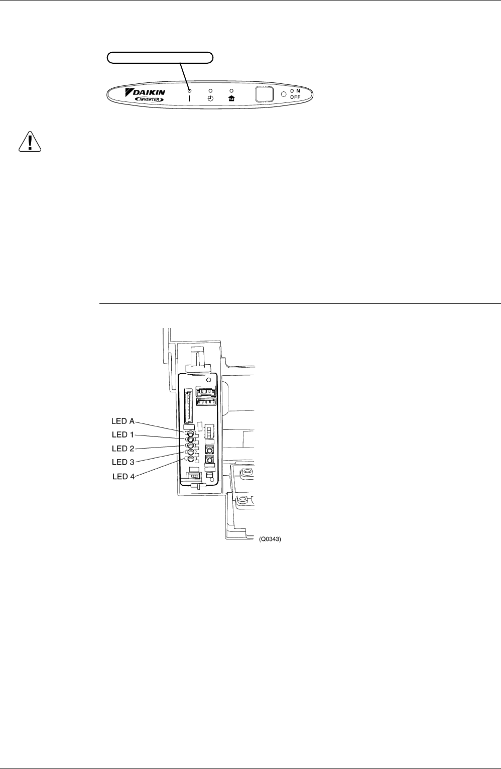
Outdoor Unit
There are green and red LEDs on the PCB. The flashing green LED indicates normal equipment
condition, and the OFF condition of the red LED indicates normal equipment condition.
(Troubleshooting with the green LED)
The LED A (green) of the outdoor unit indicate microcomputer operation condition.
Even after the error is cancelled and the equipment operates in normal condition, the LED
indication remains.
OPERATION lamp (green)
(Q0341)