
Specifications
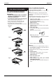

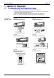
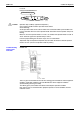
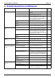
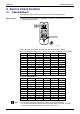
Table Of Contents
- Cover
- Table of Contents
- Part 1 List of Functions
- Part 2 Specifications
- Part 3 Printed Circuit Board Connector Wiring Diagram
- Part 4 Function and Control
- Part 5 Operation Manual
- Part 6 Service Diagnosis
- 1. Caution for Diagnosis
- 2. Problem Symptoms and Measures
- 3. Service Check Function
- 4. Code Indication on the Remote Controller
- 5. Troubleshooting
- 5.1 Indoor Units
- 5.2 Outdoor Units
- 5.3 Indoor Unit PCB Abnormality A1
- 5.4 Freeze-up Protection Control or High Pressure Control A5
- 5.5 Fan Motor or Related Abnormality A6
- 5.6 Thermistor or Related Abnormality (Indoor Unit) C4,C9
- 5.7 Front Panel Open / Close Fault C7
- 5.8 Signal Transmission Error (between Indoor and OutdoorUnit) U4
- 5.9 Unspecified Voltage (between Indoor and Outdoor Units) UA
- 5.10 Freeze-up Protection Control A5
- 5.11 Outdoor Unit PCB Abnormality E1
- 5.12 OL Activation (Compressor Overload) E5
- 5.13 Compressor Lock E6
- 5.14 DC Fan Lock E7
- 5.15 Input Over Current Detection E8
- 5.16 Discharge Pipe Temperature Control F3
- 5.17 High Pressure Control in Cooling F6
- 5.18 Compressor Sensor System Abnormality H0
- 5.19 Position Sensor Abnormality H6
- 5.20 CT or Related Abnormality H8
- 5.21 Thermistor or Related Abnormality (Outdoor Unit) P4,J3,J6,J8,J9,H9
- 5.22 Electrical Box Temperature Rise L3
- 5.23 Radiation Fin Temperature Rise L4
- 5.24 Output Over Current Detection L5
- 5.25 Insufficient Gas U0
- 5.26 Low-voltage Detection or Over-voltage Detection U2
- 5.27 Signal Transmission Error (on Outdoor Unit PCB) U7
- 5.28 Anti-icing Function in Other Rooms / UnspecifiedVoltage (between Indoor and Outdoor Units) UA,UH
- 6. Check
- Part 7 Removal Procedure
- Part 8 Others
- Part 9 Appendix
- Index
- Drawings & Flow Charts
Caution for Diagnosis SiBE12-713
226 Service Diagnosis
1. Caution for Diagnosis
1.1 Troubleshooting with Operation Lamp
The operation lamp flashes when any of the following errors is detected.
1. When a protection device of the indoor or outdoor unit is activated or when the thermistor
malfunctions, disabling equipment operation.
2. When a signal transmission error occurs between the indoor and outdoor units.
In either case, conduct the diagnostic procedure described in the following pages.
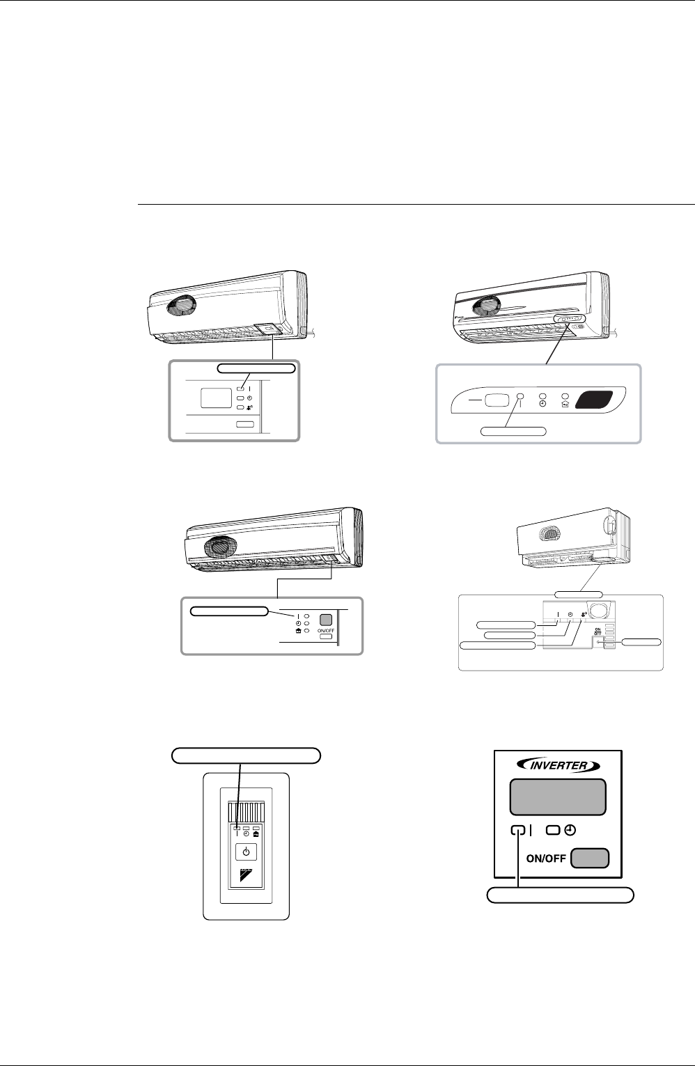
Location of
Operation Lamp
In case of In case of
FTK(X)S 20/25/35/50 D Series FTK(X)S 20/25/35 C Series
In case of
FTK(X)S 50/60/71 F Series
In case of
FTXG 25/35 E, CTXG 50 E Series
In case of
FDK(X)S 25/35/50/60 C Series
FDK(X)S 25/35 E Series
In case of
FVXS 25/35/50 F Series
(R4298)
ON/OFF
OPERATION lamp (green)
(R4297)
ON
OFF
Indicator lamps
Operation lamp (green)
(R6332)
OPERATION lamp (green)
Operation lamp (green)
INTELLIGENT EYE lamp (green)
TIMER lamp (yellow)
ON/OFF switch
Indicator lamps
(R5072)
OPERATION lamp (green)
(Q0340)
(R6843)
OPERATION lamp (green)