
Specifications
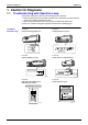
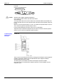
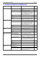
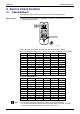
Table Of Contents
- Cover
- Table of Contents
- Part 1 List of Functions
- Part 2 Specifications
- Part 3 Printed Circuit Board Connector Wiring Diagram
- Part 4 Function and Control
- Part 5 Operation Manual
- Part 6 Service Diagnosis
- 1. Caution for Diagnosis
- 2. Problem Symptoms and Measures
- 3. Service Check Function
- 4. Code Indication on the Remote Controller
- 5. Troubleshooting
- 5.1 Indoor Units
- 5.2 Outdoor Units
- 5.3 Indoor Unit PCB Abnormality A1
- 5.4 Freeze-up Protection Control or High Pressure Control A5
- 5.5 Fan Motor or Related Abnormality A6
- 5.6 Thermistor or Related Abnormality (Indoor Unit) C4,C9
- 5.7 Front Panel Open / Close Fault C7
- 5.8 Signal Transmission Error (between Indoor and OutdoorUnit) U4
- 5.9 Unspecified Voltage (between Indoor and Outdoor Units) UA
- 5.10 Freeze-up Protection Control A5
- 5.11 Outdoor Unit PCB Abnormality E1
- 5.12 OL Activation (Compressor Overload) E5
- 5.13 Compressor Lock E6
- 5.14 DC Fan Lock E7
- 5.15 Input Over Current Detection E8
- 5.16 Discharge Pipe Temperature Control F3
- 5.17 High Pressure Control in Cooling F6
- 5.18 Compressor Sensor System Abnormality H0
- 5.19 Position Sensor Abnormality H6
- 5.20 CT or Related Abnormality H8
- 5.21 Thermistor or Related Abnormality (Outdoor Unit) P4,J3,J6,J8,J9,H9
- 5.22 Electrical Box Temperature Rise L3
- 5.23 Radiation Fin Temperature Rise L4
- 5.24 Output Over Current Detection L5
- 5.25 Insufficient Gas U0
- 5.26 Low-voltage Detection or Over-voltage Detection U2
- 5.27 Signal Transmission Error (on Outdoor Unit PCB) U7
- 5.28 Anti-icing Function in Other Rooms / UnspecifiedVoltage (between Indoor and Outdoor Units) UA,UH
- 6. Check
- Part 7 Removal Procedure
- Part 8 Others
- Part 9 Appendix
- Index
- Drawings & Flow Charts

SiBE12-713
Service Diagnosis 225
Part 6
Service Diagnosis
1. Caution for Diagnosis..........................................................................226
1.1 Troubleshooting with Operation Lamp .................................................226
2. Problem Symptoms and Measures .....................................................228
3. Service Check Function ......................................................................229
3.1 Check Method 1 ...................................................................................229
3.2 Check Method 2 ...................................................................................231
4. Code Indication on the Remote Controller ..........................................233
4.1 Error Codes and Description of Fault ...................................................233
5. Troubleshooting ..................................................................................234
5.1 Indoor Units ..........................................................................................234
5.2 Outdoor Units .......................................................................................235
5.3 Indoor Unit PCB Abnormality ...............................................................236
5.4 Freeze-up Protection Control or High Pressure Control.......................237
5.5 Fan Motor or Related Abnormality .......................................................239
5.6 Thermistor or Related Abnormality (Indoor Unit)..................................242
5.7 Front Panel Open / Close Fault............................................................243
5.8 Signal Transmission Error (between Indoor and Outdoor Unit) ...........244
5.9 Unspecified Voltage (between Indoor and Outdoor Units) ...................246
5.10 Freeze-up Protection Control ...............................................................247
5.11 Outdoor Unit PCB Abnormality.............................................................249
5.12 OL Activation (Compressor Overload) .................................................250
5.13 Compressor Lock .................................................................................251
5.14 DC Fan Lock ........................................................................................252
5.15 Input Over Current Detection ...............................................................253
5.16 Discharge Pipe Temperature Control...................................................255
5.17 High Pressure Control in Cooling .........................................................256
5.18 Compressor Sensor System Abnormality ............................................258
5.19 Position Sensor Abnormality ................................................................260
5.20 CT or Related Abnormality ...................................................................261
5.21 Thermistor or Related Abnormality (Outdoor Unit)...............................263
5.22 Electrical Box Temperature Rise..........................................................265
5.23 Radiation Fin Temperature Rise ..........................................................267
5.24 Output Over Current Detection.............................................................269
5.25 Insufficient Gas.....................................................................................271
5.26 Low-voltage Detection or Over-voltage Detection................................273
5.27 Signal Transmission Error (on Outdoor Unit PCB)...............................274
5.28 Anti-icing Function in Other Rooms / Unspecified Voltage
(between Indoor and Outdoor Units)....................................................275
6. Check ..................................................................................................276
6.1 How to Check .......................................................................................276