
Specifications
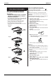
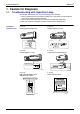
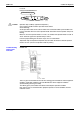
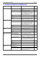
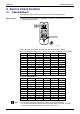
Table Of Contents
- Cover
- Table of Contents
- Part 1 List of Functions
- Part 2 Specifications
- Part 3 Printed Circuit Board Connector Wiring Diagram
- Part 4 Function and Control
- Part 5 Operation Manual
- Part 6 Service Diagnosis
- 1. Caution for Diagnosis
- 2. Problem Symptoms and Measures
- 3. Service Check Function
- 4. Code Indication on the Remote Controller
- 5. Troubleshooting
- 5.1 Indoor Units
- 5.2 Outdoor Units
- 5.3 Indoor Unit PCB Abnormality A1
- 5.4 Freeze-up Protection Control or High Pressure Control A5
- 5.5 Fan Motor or Related Abnormality A6
- 5.6 Thermistor or Related Abnormality (Indoor Unit) C4,C9
- 5.7 Front Panel Open / Close Fault C7
- 5.8 Signal Transmission Error (between Indoor and OutdoorUnit) U4
- 5.9 Unspecified Voltage (between Indoor and Outdoor Units) UA
- 5.10 Freeze-up Protection Control A5
- 5.11 Outdoor Unit PCB Abnormality E1
- 5.12 OL Activation (Compressor Overload) E5
- 5.13 Compressor Lock E6
- 5.14 DC Fan Lock E7
- 5.15 Input Over Current Detection E8
- 5.16 Discharge Pipe Temperature Control F3
- 5.17 High Pressure Control in Cooling F6
- 5.18 Compressor Sensor System Abnormality H0
- 5.19 Position Sensor Abnormality H6
- 5.20 CT or Related Abnormality H8
- 5.21 Thermistor or Related Abnormality (Outdoor Unit) P4,J3,J6,J8,J9,H9
- 5.22 Electrical Box Temperature Rise L3
- 5.23 Radiation Fin Temperature Rise L4
- 5.24 Output Over Current Detection L5
- 5.25 Insufficient Gas U0
- 5.26 Low-voltage Detection or Over-voltage Detection U2
- 5.27 Signal Transmission Error (on Outdoor Unit PCB) U7
- 5.28 Anti-icing Function in Other Rooms / UnspecifiedVoltage (between Indoor and Outdoor Units) UA,UH
- 6. Check
- Part 7 Removal Procedure
- Part 8 Others
- Part 9 Appendix
- Index
- Drawings & Flow Charts
SiBE12-713 Instruction
Operation Manual 221
HOW TO CLEAN AIR OUTLET AND OUT-
SIDE PANELS
• Clean with soft cloth.
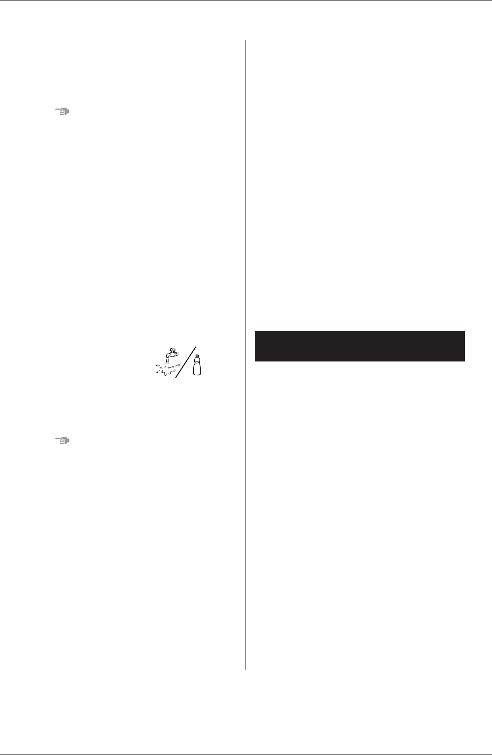
• When it is difficult to remove stains, use water or
neutral detergent.
NOTE
• Do not use gasoline, benzene, thinner, polishing
powder, liquid insecticide. It may cause discolor-
ing or warping.
• Do not let the indoor unit get wet. It may cause an
electric shock or a fire.
• Do not use water or air of 50˚C or higher for clean-
ing air filters and outside panels.
HOW TO CLEAN THE SUCTION GRILLE
1. Open the suction grille.
Slide both knobs and then pull them downward.
(Do the same procedure for closing.)
2. Remove the air filter.
Refer to “HOW TO CLEAN THE AIR FILTER”.
(Refer to Fig. 3)
3. Remove the suction grille.
Open the suction grille and pull the clips on the
back of the suction grille forward.
(Refer to Fig. 4)
4. Clean the suction grille.
Wash with a soft bristle
brush and neutral deter-
gent or water, and dry
throughly.
• When very grimy
Directly apply the type of detergent used for
cleaning ventilation fans or ovens, wait 10 min-
utes, and then rinse with water.
NOTE
• Do not wash the air conditioner with hot water of
more than 50˚C, as doing so may result in discol-
oration and/or deformation.
5. Fix the air filter.
Refer to “HOW TO CLEAN THE AIR FILTER ”.
6. Fix the suction grille.
Refer to item No. 3.
7. Close the suction grille.
Refer to item No. 1.
START UP AFTER A LONG STOP
Confirm the following
• Check that the air inlet and outlet are not blocked.
Remove any obstacle.
• Check if the earth is connected.
Might there be a broken wire somewhere?
Contact your dealer if there are any problems
Clean the air filter and outside panels
• After cleaning the air filter, make sure to attach it.
Turn on the main power supply switch
• The display on the remote controller will be shown
when the power is turned on.
• To protect the unit, turn on the main power switch
at least 6 hours before operation.
WHAT TO DO WHEN STOPPING THE SYS-
TEM FOR A LONG PERIOD
Turn on FAN OPERATION for a half day and dry
the unit.
• Refer to “6. OPERATION PROCEDURE”.
Cut off the power supply.
• When the main power switch is turned on, some
watts of electricity is being used even if the sys-
tem is not operating.
Turn off the main power supply switch for saving
energy.
• The display on the remote controller will vanish
when the main power switch is turned off.
Clean the air filter and the exterior.
• Be sure to replace the air filter to its original place
after cleaning. Refer to “MAINTENANCE”.
The following symptoms do not indicate air condi-
tioner malfunction
I. THE SYSTEM DOES NOT OPERATE
• The system does not restart immediately after
the ON/OFF BUTTON is pressed.
If the OPERATION lamp lights, the system is in
normal condition.
It does not restart immediately because a safety
device operates to prevent overload of the sys-
tem. After 3 minutes, the system will turn on again
automatically.
• The system does not restart immediately
when TEMPERATURE SETTING button is
returned to the former position after pushing
the button.
If the OPERATION lamp lights, the system is in
normal condition.
It does not restart immediately because a safety
device operates to prevent overload of the sys-
tem. After 3 minutes, the system will turn on again
automatically.
9. NOT MALFUNCTION OF THE AIR
CONDITIONER