
Specifications
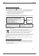
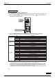
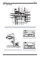
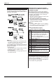
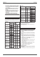
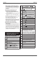
Table Of Contents
- Cover
- Table of Contents
- Part 1 List of Functions
- Part 2 Specifications
- Part 3 Printed Circuit Board Connector Wiring Diagram
- Part 4 Function and Control
- Part 5 Operation Manual
- Part 6 Service Diagnosis
- 1. Caution for Diagnosis
- 2. Problem Symptoms and Measures
- 3. Service Check Function
- 4. Code Indication on the Remote Controller
- 5. Troubleshooting
- 5.1 Indoor Units
- 5.2 Outdoor Units
- 5.3 Indoor Unit PCB Abnormality A1
- 5.4 Freeze-up Protection Control or High Pressure Control A5
- 5.5 Fan Motor or Related Abnormality A6
- 5.6 Thermistor or Related Abnormality (Indoor Unit) C4,C9
- 5.7 Front Panel Open / Close Fault C7
- 5.8 Signal Transmission Error (between Indoor and OutdoorUnit) U4
- 5.9 Unspecified Voltage (between Indoor and Outdoor Units) UA
- 5.10 Freeze-up Protection Control A5
- 5.11 Outdoor Unit PCB Abnormality E1
- 5.12 OL Activation (Compressor Overload) E5
- 5.13 Compressor Lock E6
- 5.14 DC Fan Lock E7
- 5.15 Input Over Current Detection E8
- 5.16 Discharge Pipe Temperature Control F3
- 5.17 High Pressure Control in Cooling F6
- 5.18 Compressor Sensor System Abnormality H0
- 5.19 Position Sensor Abnormality H6
- 5.20 CT or Related Abnormality H8
- 5.21 Thermistor or Related Abnormality (Outdoor Unit) P4,J3,J6,J8,J9,H9
- 5.22 Electrical Box Temperature Rise L3
- 5.23 Radiation Fin Temperature Rise L4
- 5.24 Output Over Current Detection L5
- 5.25 Insufficient Gas U0
- 5.26 Low-voltage Detection or Over-voltage Detection U2
- 5.27 Signal Transmission Error (on Outdoor Unit PCB) U7
- 5.28 Anti-icing Function in Other Rooms / UnspecifiedVoltage (between Indoor and Outdoor Units) UA,UH
- 6. Check
- Part 7 Removal Procedure
- Part 8 Others
- Part 9 Appendix
- Index
- Drawings & Flow Charts
SiBE12-713 Instruction
Operation Manual 219
Operate in the following order.
• The timer is operated in the following two ways.
• Programming the stop time ( )
.... The system stops
operating after the set time has elapsed.
• Programming the start time ( )
.... The system starts
operating after the set time has elapsed.
• The timer can be programmed a maximum of 72
hours.
• The start and the stop time can be simultaneously
programmed.
TIMER MODE START/STO
P
Press the TIMER MODE START/STOP button
several times and select the mode on the
display.
The display flashes.
For setting the timer stop .... “ ”
For setting the timer start .... “ ”
PROGRAMMING TIME
Press the PROGRAMMING TIME button and
set the time for stopping or starting the sys-
tem.
When this button is pressed, the time
advances by 1 hour.
When this button is pressed, the time
goes backward by 1 hour.
TIMER ON/OFF
Press the TIMER ON/OFF BUTTON.
The timer setting procedure ends.
The display “ or ” changes from flash-
ing light to a constant light.
Refer to figure 4 on page [1]
NOTE
• When setting the timer Off and On at the same
time, repeat the above procedure from to
once again.
When the timer is programmed to stop the system
after 3 hours and start the system after 4 hours, the
system will stop after 3 hours and then 1 hour later
the system will start.
• After the timer is programmed, the display shows
the remaining time.
PROGRAM TIMER OPERATION
1
2
3
1
3
• Press the TIMER ON/OFF BUTTON once again
to cancel programming. The display vanishes.
Observe the following precautions to ensure the
system operates.
• Adjust the room temperature properly for a com-
fortable environment. Avoid excessive heating or
cooling.
• Prevent direct sunlight from entering a room dur-
ing cooling operation by using curtains or blinds.
• Ventilate the room regularly.
Using the unit for long periods of time requires
attentive ventilation of the room.
• Keep doors and windows closed. If the doors and
windows remain open, room air will flow out and
cause to decrease the effect of cooling and heat-
ing.
• Do not place other heaters directly below the
indoor unit.
They may deform due to the heat.
• Never place objects near the air inlet and the air
outlet of the unit. It may cause deterioration in the
effect or stop in the operation.
• Turn off the main power supply switch when it is
not used for long periods of time. When the main
power switch is turned on, some watts of electric-
ity is being used even if the system is not operat-
ing. Turn off the main power supply switch for
saving energy. When reoperating, turn on the
main power supply switch 6hours before opera-
tion for smooth running (Refer to MAINTE-
NANCE).
• When the display shows “ ” (TIME TO CLEAN
AIR FILTER), ask a qualified service person to
clean the filters (Refer to MAINTENANCE).
7. OPTIMUM OPERATION