
Specifications
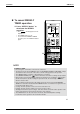
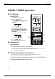
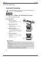
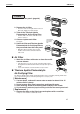
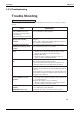
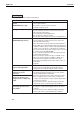
Table Of Contents
- Cover
- Table of Contents
- Part 1 List of Functions
- Part 2 Specifications
- Part 3 Printed Circuit Board Connector Wiring Diagram
- Part 4 Function and Control
- Part 5 Operation Manual
- Part 6 Service Diagnosis
- 1. Caution for Diagnosis
- 2. Problem Symptoms and Measures
- 3. Service Check Function
- 4. Code Indication on the Remote Controller
- 5. Troubleshooting
- 5.1 Indoor Units
- 5.2 Outdoor Units
- 5.3 Indoor Unit PCB Abnormality A1
- 5.4 Freeze-up Protection Control or High Pressure Control A5
- 5.5 Fan Motor or Related Abnormality A6
- 5.6 Thermistor or Related Abnormality (Indoor Unit) C4,C9
- 5.7 Front Panel Open / Close Fault C7
- 5.8 Signal Transmission Error (between Indoor and OutdoorUnit) U4
- 5.9 Unspecified Voltage (between Indoor and Outdoor Units) UA
- 5.10 Freeze-up Protection Control A5
- 5.11 Outdoor Unit PCB Abnormality E1
- 5.12 OL Activation (Compressor Overload) E5
- 5.13 Compressor Lock E6
- 5.14 DC Fan Lock E7
- 5.15 Input Over Current Detection E8
- 5.16 Discharge Pipe Temperature Control F3
- 5.17 High Pressure Control in Cooling F6
- 5.18 Compressor Sensor System Abnormality H0
- 5.19 Position Sensor Abnormality H6
- 5.20 CT or Related Abnormality H8
- 5.21 Thermistor or Related Abnormality (Outdoor Unit) P4,J3,J6,J8,J9,H9
- 5.22 Electrical Box Temperature Rise L3
- 5.23 Radiation Fin Temperature Rise L4
- 5.24 Output Over Current Detection L5
- 5.25 Insufficient Gas U0
- 5.26 Low-voltage Detection or Over-voltage Detection U2
- 5.27 Signal Transmission Error (on Outdoor Unit PCB) U7
- 5.28 Anti-icing Function in Other Rooms / UnspecifiedVoltage (between Indoor and Outdoor Units) UA,UH
- 6. Check
- Part 7 Removal Procedure
- Part 8 Others
- Part 9 Appendix
- Index
- Drawings & Flow Charts
Instruction SiBE12-713
202 Operation Manual
23
Setting WEEKLY TIMER
using copy mode
•
A reservation made once can be easily copied and
the same settings used for another day of the week.
1. Press “ button”.
2.
Press “SELECT button” to confirm
the day of the week to be copied.
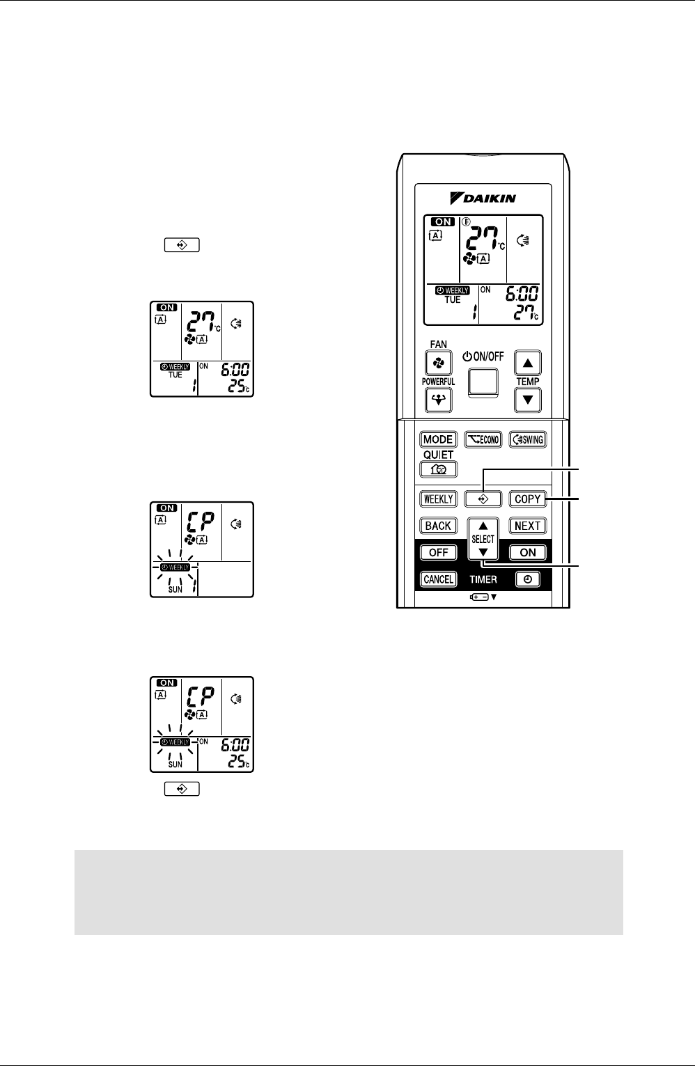
3. Press “COPY button”.
• This activates copy mode.
•
Copy whole reservation of the selected day of the week.
4.
Press “SELECT button” to select
the destination day of the week.
5. Press “COPY button”.
• The reservation will be copied to the selected day of the week. The whole reservation of the
selected day of the week will be copied.
• The reservation can be copied to another day of the week in succession.
6. Press “ button”.
• Exit copy mode.
NOTE
COPY MODE
• The entire reservation of the source day of the week is copied in the copy mode.
Detailed settings can be made after the copy is completed.
•
Both WEEKLY TIMER and ON/OFF timer cannot be used at the same time. The ON/OFF timer has priority if it is set
while WEEKLY TIMER is still active. WEEKLY TIMER is activated after the reserved ON/OFF timer is completed.
3, 5
1, 6
2, 4