
Specifications
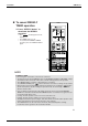
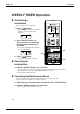
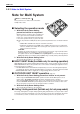
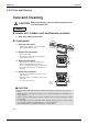
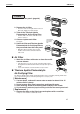
Table Of Contents
- Cover
- Table of Contents
- Part 1 List of Functions
- Part 2 Specifications
- Part 3 Printed Circuit Board Connector Wiring Diagram
- Part 4 Function and Control
- Part 5 Operation Manual
- Part 6 Service Diagnosis
- 1. Caution for Diagnosis
- 2. Problem Symptoms and Measures
- 3. Service Check Function
- 4. Code Indication on the Remote Controller
- 5. Troubleshooting
- 5.1 Indoor Units
- 5.2 Outdoor Units
- 5.3 Indoor Unit PCB Abnormality A1
- 5.4 Freeze-up Protection Control or High Pressure Control A5
- 5.5 Fan Motor or Related Abnormality A6
- 5.6 Thermistor or Related Abnormality (Indoor Unit) C4,C9
- 5.7 Front Panel Open / Close Fault C7
- 5.8 Signal Transmission Error (between Indoor and OutdoorUnit) U4
- 5.9 Unspecified Voltage (between Indoor and Outdoor Units) UA
- 5.10 Freeze-up Protection Control A5
- 5.11 Outdoor Unit PCB Abnormality E1
- 5.12 OL Activation (Compressor Overload) E5
- 5.13 Compressor Lock E6
- 5.14 DC Fan Lock E7
- 5.15 Input Over Current Detection E8
- 5.16 Discharge Pipe Temperature Control F3
- 5.17 High Pressure Control in Cooling F6
- 5.18 Compressor Sensor System Abnormality H0
- 5.19 Position Sensor Abnormality H6
- 5.20 CT or Related Abnormality H8
- 5.21 Thermistor or Related Abnormality (Outdoor Unit) P4,J3,J6,J8,J9,H9
- 5.22 Electrical Box Temperature Rise L3
- 5.23 Radiation Fin Temperature Rise L4
- 5.24 Output Over Current Detection L5
- 5.25 Insufficient Gas U0
- 5.26 Low-voltage Detection or Over-voltage Detection U2
- 5.27 Signal Transmission Error (on Outdoor Unit PCB) U7
- 5.28 Anti-icing Function in Other Rooms / UnspecifiedVoltage (between Indoor and Outdoor Units) UA,UH
- 6. Check
- Part 7 Removal Procedure
- Part 8 Others
- Part 9 Appendix
- Index
- Drawings & Flow Charts
Instruction SiBE12-713
200 Operation Manual
21
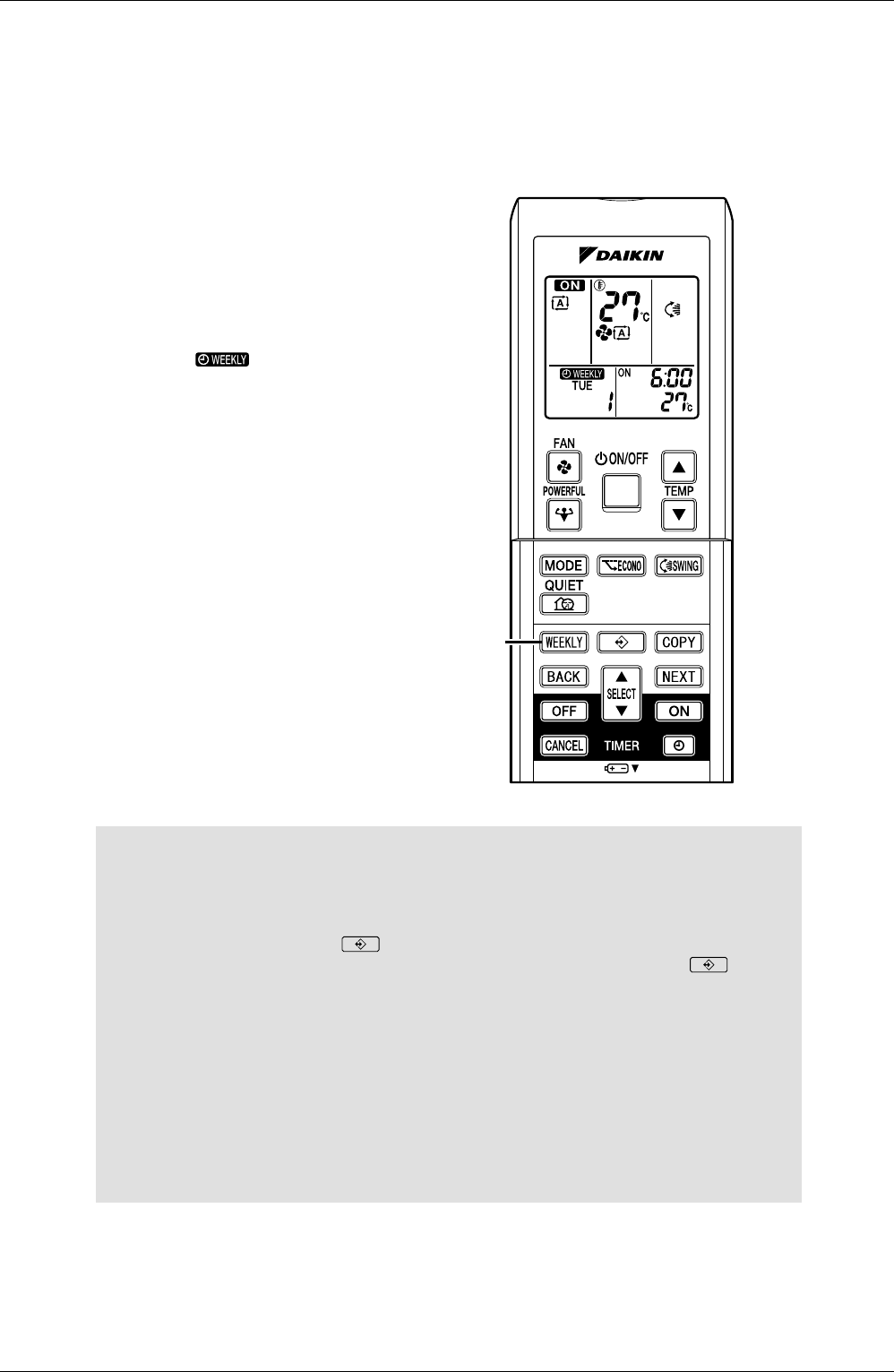
To cancel WEEKLY
TIMER operation
11.Press “WEEKLY button” to
deactivate the WEEKLY
operation.
• The “ ” will disappear from the
display.
• The TIMER lamp goes off.
• To reactivate the WEEKLY TIMER
operation, press the “WEEKLY button”
again.
NOTE
WEEKLY TIMER
• Do not forget to set the time on the remote control first.
•
The day of the week, time and ON/OFF can be set with WEEKLY TIMER. For ON-TIMER, settings
other than the above are based on the remote controller settings just before the operation.
• The “WEEKLY button” activates or deactivates the reservation.
•
To set WEEKLY TIMER, press “ button” and make a reservation according to the procedures.
• Only the time and set temperature set with the weekly timer are sent with the “ button”.
Set the weekly timer only after setting the operation mode, the fan strength, and the fan
direction ahead of time.
• Up to 4 settings per day and up to 28 settings per week can be reserved with WEEKLY
TIMER. If a reservation deactivated with “WEEKLY button” is activated once again, the last
reservation made will be used.
• Cooling: The unit operates at 18˚C even if it is set at 10 to 17˚C.
• Heating: The unit operates at 30˚C even if it is set at 31 to 32˚C.
• Shutting the breaker off, power outages, and other similar events will render operation of the
indoor unit’s internal clock inaccurate. Reset the clock. (page 8.)
• The “BACK button” can be used only for the mode, time and temperature settings.
It cannot be used to go back to the reservation number.
11