
Specifications
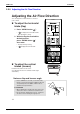
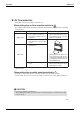
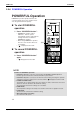
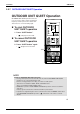
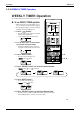
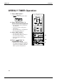
Table Of Contents
- Cover
- Table of Contents
- Part 1 List of Functions
- Part 2 Specifications
- Part 3 Printed Circuit Board Connector Wiring Diagram
- Part 4 Function and Control
- Part 5 Operation Manual
- Part 6 Service Diagnosis
- 1. Caution for Diagnosis
- 2. Problem Symptoms and Measures
- 3. Service Check Function
- 4. Code Indication on the Remote Controller
- 5. Troubleshooting
- 5.1 Indoor Units
- 5.2 Outdoor Units
- 5.3 Indoor Unit PCB Abnormality A1
- 5.4 Freeze-up Protection Control or High Pressure Control A5
- 5.5 Fan Motor or Related Abnormality A6
- 5.6 Thermistor or Related Abnormality (Indoor Unit) C4,C9
- 5.7 Front Panel Open / Close Fault C7
- 5.8 Signal Transmission Error (between Indoor and OutdoorUnit) U4
- 5.9 Unspecified Voltage (between Indoor and Outdoor Units) UA
- 5.10 Freeze-up Protection Control A5
- 5.11 Outdoor Unit PCB Abnormality E1
- 5.12 OL Activation (Compressor Overload) E5
- 5.13 Compressor Lock E6
- 5.14 DC Fan Lock E7
- 5.15 Input Over Current Detection E8
- 5.16 Discharge Pipe Temperature Control F3
- 5.17 High Pressure Control in Cooling F6
- 5.18 Compressor Sensor System Abnormality H0
- 5.19 Position Sensor Abnormality H6
- 5.20 CT or Related Abnormality H8
- 5.21 Thermistor or Related Abnormality (Outdoor Unit) P4,J3,J6,J8,J9,H9
- 5.22 Electrical Box Temperature Rise L3
- 5.23 Radiation Fin Temperature Rise L4
- 5.24 Output Over Current Detection L5
- 5.25 Insufficient Gas U0
- 5.26 Low-voltage Detection or Over-voltage Detection U2
- 5.27 Signal Transmission Error (on Outdoor Unit PCB) U7
- 5.28 Anti-icing Function in Other Rooms / UnspecifiedVoltage (between Indoor and Outdoor Units) UA,UH
- 6. Check
- Part 7 Removal Procedure
- Part 8 Others
- Part 9 Appendix
- Index
- Drawings & Flow Charts
Instruction SiBE12-713
192 Operation Manual
13
Air flow selection
• Make air flow selection according to what suits you.
When setting the air flow selection switch to .
• Air conditioner automatically decides the appropriate blowing pattern depending on the operating
mode/situation.
• During Dry mode, so that cold air does not come into direct contact with people, air is blown
upper air outlet.
When setting the air outlet selection switch to .
• Regardless of the operating mode or situation, air blows from the upper air outlet.
• Use this switch when you do not want air coming out of the lower air outlet. (While sleeping etc.)
CAUTION
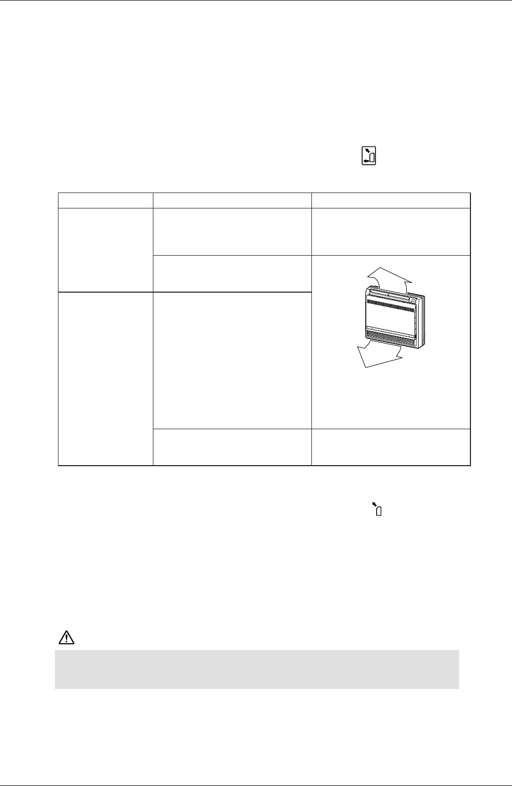
Operating mode Situation Blowing pattern
COOL mode
• When the room has become fully
cool, or when one hour has
passed since turning on the air
conditioner.
• So that air does not come into
direct contact with people, air is
blown upper air outlet, room tem-
perature is equalized.
• At start of operation or other
times when the room is not fully
cooled.
• Air is blown from the upper and
lower air outlets for high speed
cooling during COOL mode, and
for filling the room with warm air
during HEAT mode.
HEAT mode
• At times other than below.
(Normal time.)
• At start or when air temperature
is low.
• So that air does not come into
direct contact with people. Air is
blown upper air outlet.
• Do not try to adjust the flap by hand.
• When adjusting by hand, the mechanism may not operate properly or condensation may drip
from air outlets.