
Specifications
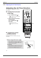
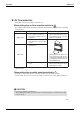
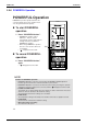
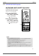
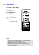
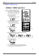
Table Of Contents
- Cover
- Table of Contents
- Part 1 List of Functions
- Part 2 Specifications
- Part 3 Printed Circuit Board Connector Wiring Diagram
- Part 4 Function and Control
- Part 5 Operation Manual
- Part 6 Service Diagnosis
- 1. Caution for Diagnosis
- 2. Problem Symptoms and Measures
- 3. Service Check Function
- 4. Code Indication on the Remote Controller
- 5. Troubleshooting
- 5.1 Indoor Units
- 5.2 Outdoor Units
- 5.3 Indoor Unit PCB Abnormality A1
- 5.4 Freeze-up Protection Control or High Pressure Control A5
- 5.5 Fan Motor or Related Abnormality A6
- 5.6 Thermistor or Related Abnormality (Indoor Unit) C4,C9
- 5.7 Front Panel Open / Close Fault C7
- 5.8 Signal Transmission Error (between Indoor and OutdoorUnit) U4
- 5.9 Unspecified Voltage (between Indoor and Outdoor Units) UA
- 5.10 Freeze-up Protection Control A5
- 5.11 Outdoor Unit PCB Abnormality E1
- 5.12 OL Activation (Compressor Overload) E5
- 5.13 Compressor Lock E6
- 5.14 DC Fan Lock E7
- 5.15 Input Over Current Detection E8
- 5.16 Discharge Pipe Temperature Control F3
- 5.17 High Pressure Control in Cooling F6
- 5.18 Compressor Sensor System Abnormality H0
- 5.19 Position Sensor Abnormality H6
- 5.20 CT or Related Abnormality H8
- 5.21 Thermistor or Related Abnormality (Outdoor Unit) P4,J3,J6,J8,J9,H9
- 5.22 Electrical Box Temperature Rise L3
- 5.23 Radiation Fin Temperature Rise L4
- 5.24 Output Over Current Detection L5
- 5.25 Insufficient Gas U0
- 5.26 Low-voltage Detection or Over-voltage Detection U2
- 5.27 Signal Transmission Error (on Outdoor Unit PCB) U7
- 5.28 Anti-icing Function in Other Rooms / UnspecifiedVoltage (between Indoor and Outdoor Units) UA,UH
- 6. Check
- Part 7 Removal Procedure
- Part 8 Others
- Part 9 Appendix
- Index
- Drawings & Flow Charts
SiBE12-713 Instruction
Operation Manual 191
2.2.5 Adjusting the Air Flow Direction
12
Adjusting the Air Flow Direction
You can adjust the air flow direction to increase
your comfort.
To adjust the horizontal
blade (flap)
1. Press “SWING button ”.
• “ ” is displayed on the LCD and the
flaps will begin to swing.
2. When the flap has reached the
desired position,
press “SWING button ”
once more.
• The flap will stop moving.
• “ ” disappears from the LCD.
To adjust the vertical
blades (louvers)
Hold the knob and move the louver.
(You will find a knob on the left-side and the right-
side blades.)
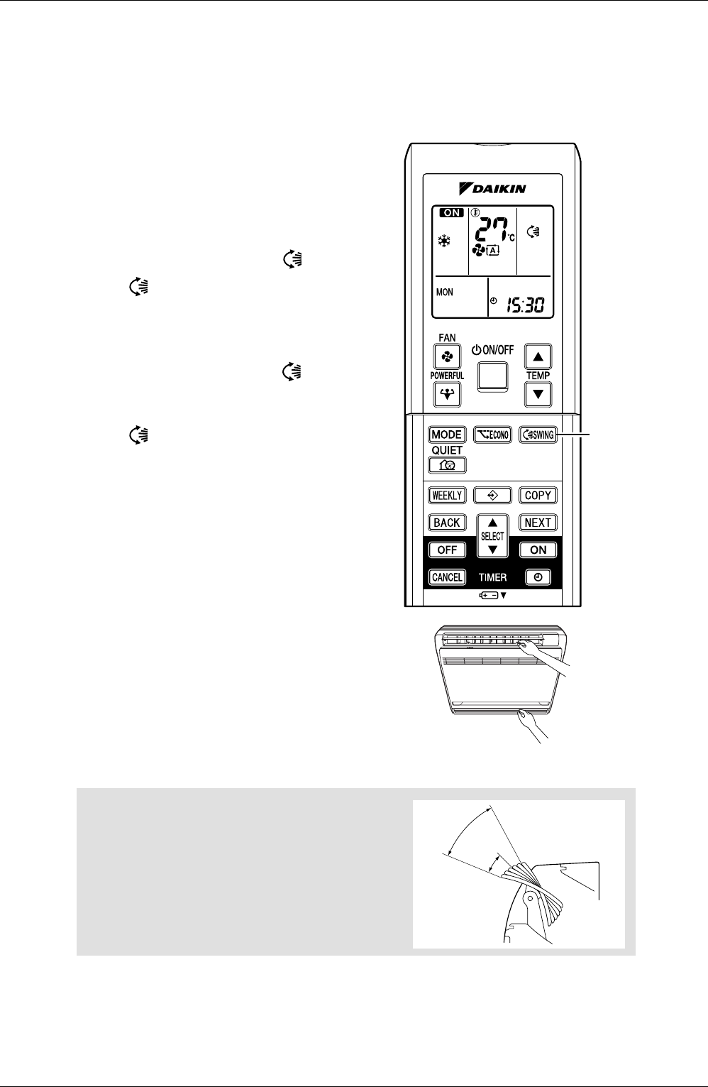
Notes on flap and louvers angle
• Unless “SWING” is selected, you should set the
flap at a near-horizontal angle in HEAT mode and
at a upward position in COOL or DRY mode to
obtain the best performance.
ATTENTION
• When adjusting the flap by hand, turn off the unit,
and use the remote controller to restart the unit.
• Be careful when adjusting the louvers. Inside the
air outlet, a fan is rotating at a high speed.
1, 2
COOL/
DRY
HEAT