
Specifications
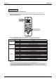
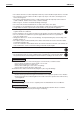
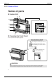
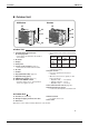
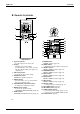
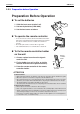
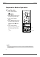
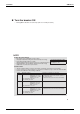
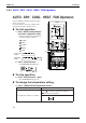
Table Of Contents
- Cover
- Table of Contents
- Part 1 List of Functions
- Part 2 Specifications
- Part 3 Printed Circuit Board Connector Wiring Diagram
- Part 4 Function and Control
- Part 5 Operation Manual
- Part 6 Service Diagnosis
- 1. Caution for Diagnosis
- 2. Problem Symptoms and Measures
- 3. Service Check Function
- 4. Code Indication on the Remote Controller
- 5. Troubleshooting
- 5.1 Indoor Units
- 5.2 Outdoor Units
- 5.3 Indoor Unit PCB Abnormality A1
- 5.4 Freeze-up Protection Control or High Pressure Control A5
- 5.5 Fan Motor or Related Abnormality A6
- 5.6 Thermistor or Related Abnormality (Indoor Unit) C4,C9
- 5.7 Front Panel Open / Close Fault C7
- 5.8 Signal Transmission Error (between Indoor and OutdoorUnit) U4
- 5.9 Unspecified Voltage (between Indoor and Outdoor Units) UA
- 5.10 Freeze-up Protection Control A5
- 5.11 Outdoor Unit PCB Abnormality E1
- 5.12 OL Activation (Compressor Overload) E5
- 5.13 Compressor Lock E6
- 5.14 DC Fan Lock E7
- 5.15 Input Over Current Detection E8
- 5.16 Discharge Pipe Temperature Control F3
- 5.17 High Pressure Control in Cooling F6
- 5.18 Compressor Sensor System Abnormality H0
- 5.19 Position Sensor Abnormality H6
- 5.20 CT or Related Abnormality H8
- 5.21 Thermistor or Related Abnormality (Outdoor Unit) P4,J3,J6,J8,J9,H9
- 5.22 Electrical Box Temperature Rise L3
- 5.23 Radiation Fin Temperature Rise L4
- 5.24 Output Over Current Detection L5
- 5.25 Insufficient Gas U0
- 5.26 Low-voltage Detection or Over-voltage Detection U2
- 5.27 Signal Transmission Error (on Outdoor Unit PCB) U7
- 5.28 Anti-icing Function in Other Rooms / UnspecifiedVoltage (between Indoor and Outdoor Units) UA,UH
- 6. Check
- Part 7 Removal Procedure
- Part 8 Others
- Part 9 Appendix
- Index
- Drawings & Flow Charts
Instruction SiBE12-713
186 Operation Manual
2.2.3 Preparation before Operation
7
Preparation Before Operation
To set the batteries
1. Slide the front cover to take it off.
2. Set two dry batteries (LR03·AAA).
3. Set the front cover as before.
To operate the remote controller
• To use the remote controller, aim the transmitter at the indoor
unit. If there is anything to block signals between the unit and
the remote controller, such as a curtain, the unit will not
operate.
• Do not drop the remote controller. Do not get it wet.
• The maximum distance for communication is about 7m.
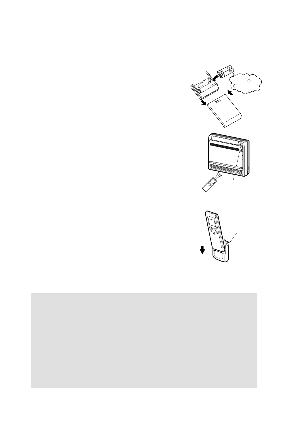
To fix the remote controller holder
on the wall
1. Choose a place from where the signals
reach the unit.
2. Fix the holder to a wall, a pillar, or similar
location with the screws procured locally.
3. Place the remote controller in the remote
controller holder.
ATTENTION
About batteries
• When replacing the batteries, use batteries of the same type, and replace the two old batteries together.
• When the system is not used for a long time, take the batteries out.
• We recommend replacing once a year, although if the remote controller display begins to fade or if reception
deteriorates, please replace with new alkaline batteries. Using manganese batteries reduces the li fespan.
• The attached batteries are provided for the initial use of the system.
The usable period of the batteries may be short depending on the manufactured date of the air conditioner.
About remote controller
• Never expose the remote controller to direct sunlight.
• Dust on the signal transmitter or receiver will reduce the sensitivity. Wipe off dust with soft cloth.
• Signal communication may be disabled if an electronic-starter-type fluorescent lamp (such
as inverter-type lamps) is in the room. Consult the shop if that is the case.
• If the remote controller signals happen to operate another appliance, move that appliance
to somewhere else, or consult the shop.
2
3
1
Position
+
and
correctly!
–
Receiver
Remote
controller
holder
Set.
• To remove, pull it
upwards.