
Specifications
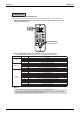
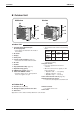
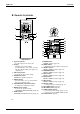
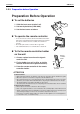
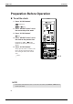
Table Of Contents
- Cover
- Table of Contents
- Part 1 List of Functions
- Part 2 Specifications
- Part 3 Printed Circuit Board Connector Wiring Diagram
- Part 4 Function and Control
- Part 5 Operation Manual
- Part 6 Service Diagnosis
- 1. Caution for Diagnosis
- 2. Problem Symptoms and Measures
- 3. Service Check Function
- 4. Code Indication on the Remote Controller
- 5. Troubleshooting
- 5.1 Indoor Units
- 5.2 Outdoor Units
- 5.3 Indoor Unit PCB Abnormality A1
- 5.4 Freeze-up Protection Control or High Pressure Control A5
- 5.5 Fan Motor or Related Abnormality A6
- 5.6 Thermistor or Related Abnormality (Indoor Unit) C4,C9
- 5.7 Front Panel Open / Close Fault C7
- 5.8 Signal Transmission Error (between Indoor and OutdoorUnit) U4
- 5.9 Unspecified Voltage (between Indoor and Outdoor Units) UA
- 5.10 Freeze-up Protection Control A5
- 5.11 Outdoor Unit PCB Abnormality E1
- 5.12 OL Activation (Compressor Overload) E5
- 5.13 Compressor Lock E6
- 5.14 DC Fan Lock E7
- 5.15 Input Over Current Detection E8
- 5.16 Discharge Pipe Temperature Control F3
- 5.17 High Pressure Control in Cooling F6
- 5.18 Compressor Sensor System Abnormality H0
- 5.19 Position Sensor Abnormality H6
- 5.20 CT or Related Abnormality H8
- 5.21 Thermistor or Related Abnormality (Outdoor Unit) P4,J3,J6,J8,J9,H9
- 5.22 Electrical Box Temperature Rise L3
- 5.23 Radiation Fin Temperature Rise L4
- 5.24 Output Over Current Detection L5
- 5.25 Insufficient Gas U0
- 5.26 Low-voltage Detection or Over-voltage Detection U2
- 5.27 Signal Transmission Error (on Outdoor Unit PCB) U7
- 5.28 Anti-icing Function in Other Rooms / UnspecifiedVoltage (between Indoor and Outdoor Units) UA,UH
- 6. Check
- Part 7 Removal Procedure
- Part 8 Others
- Part 9 Appendix
- Index
- Drawings & Flow Charts
SiBE12-713 Instruction
Operation Manual 185
6
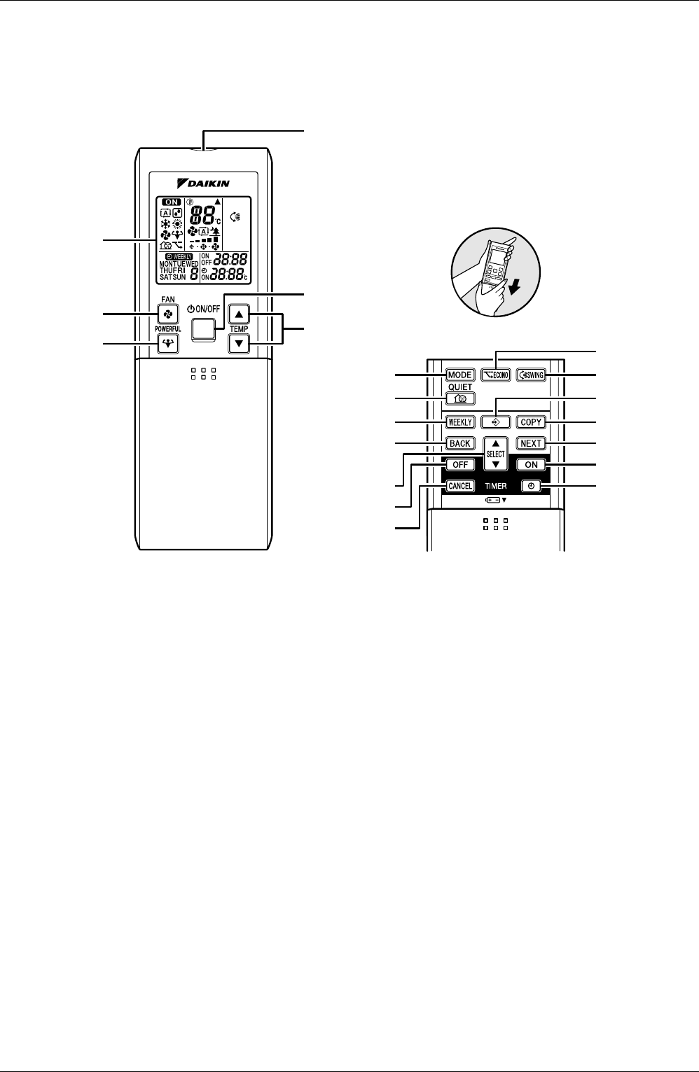
Remote Controller
1. Signal transmitter:
• It sends signals to the indoor unit.
2. Display:
• It displays the current settings.
(In this illustration, each section is shown
with all its displays ON for the purpose of
explanation.)
3. FAN setting button:
• It selects the air flow rate setting.
4. POWERFUL button:
POWERFUL operation (page 14.)
5. ON/OFF button:
• Press this button once to start operation.
Press once again to stop it.
6. TEMPERATURE adjustment buttons:
• It changes the temperature setting.
7. MODE selector button:
• It selects the operation mode.
(AUTO/DRY/COOL/HEAT/FAN) (page 10.)
8. QUIET button:
OUTDOOR UNIT QUIET operation (page 15.)
9. ECONO button:
ECONO operation (page 16.)
10. SWING button:
• Adjusting the Air Flow Direction (page 12.)
11. WEEKLY button:
WEEKLY TIMER operation (page 19.)
12. PROGRAM button:
WEEKLY TIMER operation (page 19.)
13. COPY button:
WEEKLY TIMER operation (page 19.)
14. BACK button:
WEEKLY TIMER operation (page 19.)
15. NEXT button:
WEEKLY TIMER operation (page 19.)
16. SELECT button:
• It changes the timer setting.
(page 17.)
17. OFF TIMER button:
(page 17.)
18. ON TIMER button:
(page 18.)
19. TIMER CANCEL button:
• It cancels the timer setting. (page 17, 18.)
•
It cannot be used for the WEEKLY TIMER operation.
20. CLOCK button: (page 8.)
1
5
6
2
3
4
<ARC452A1>
7
8
11
14
16
17
19
<Open the lid>
9
10
12
13
15
18
20