
Specifications
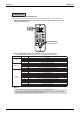
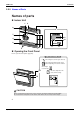
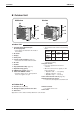
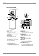
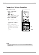
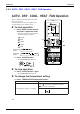
Table Of Contents
- Cover
- Table of Contents
- Part 1 List of Functions
- Part 2 Specifications
- Part 3 Printed Circuit Board Connector Wiring Diagram
- Part 4 Function and Control
- Part 5 Operation Manual
- Part 6 Service Diagnosis
- 1. Caution for Diagnosis
- 2. Problem Symptoms and Measures
- 3. Service Check Function
- 4. Code Indication on the Remote Controller
- 5. Troubleshooting
- 5.1 Indoor Units
- 5.2 Outdoor Units
- 5.3 Indoor Unit PCB Abnormality A1
- 5.4 Freeze-up Protection Control or High Pressure Control A5
- 5.5 Fan Motor or Related Abnormality A6
- 5.6 Thermistor or Related Abnormality (Indoor Unit) C4,C9
- 5.7 Front Panel Open / Close Fault C7
- 5.8 Signal Transmission Error (between Indoor and OutdoorUnit) U4
- 5.9 Unspecified Voltage (between Indoor and Outdoor Units) UA
- 5.10 Freeze-up Protection Control A5
- 5.11 Outdoor Unit PCB Abnormality E1
- 5.12 OL Activation (Compressor Overload) E5
- 5.13 Compressor Lock E6
- 5.14 DC Fan Lock E7
- 5.15 Input Over Current Detection E8
- 5.16 Discharge Pipe Temperature Control F3
- 5.17 High Pressure Control in Cooling F6
- 5.18 Compressor Sensor System Abnormality H0
- 5.19 Position Sensor Abnormality H6
- 5.20 CT or Related Abnormality H8
- 5.21 Thermistor or Related Abnormality (Outdoor Unit) P4,J3,J6,J8,J9,H9
- 5.22 Electrical Box Temperature Rise L3
- 5.23 Radiation Fin Temperature Rise L4
- 5.24 Output Over Current Detection L5
- 5.25 Insufficient Gas U0
- 5.26 Low-voltage Detection or Over-voltage Detection U2
- 5.27 Signal Transmission Error (on Outdoor Unit PCB) U7
- 5.28 Anti-icing Function in Other Rooms / UnspecifiedVoltage (between Indoor and Outdoor Units) UA,UH
- 6. Check
- Part 7 Removal Procedure
- Part 8 Others
- Part 9 Appendix
- Index
- Drawings & Flow Charts
Instruction SiBE12-713
184 Operation Manual
5
Outdoor Unit
Indoor Unit
1. Titanium Apatite Photocatalytic
Air-Purifying Filter:
• These filters are attached to the inside of
the air filters.
2. Air outlet
3. Display
4. Front panel
5. Louvers (vertical blades):
(page 12.)
• The louvers are inside of the air outlet.
6. Air inlet
7. Air filter
8. Flap (horizontal blade):
(page 12.)
9. Operation lamp (green)
10. TIMER lamp (yellow): (page 17.)
11. Indoor Unit ON/OFF switch:
• Push this switch once to start operation.
Push once again to stop it.
• The operation mode refers to the following
table.
• This switch is useful when the remote
controller is missing.
12. Signal receiver:
• It receives signals from the remote
controller.
• When the unit receives a signal, you will
hear a short beep.
• Operation start ........ beep-beep
• Settings changed ..... beep
• Operation stop.......... beeeeep
13. Air outlet selection switch:
(page 13.)
14. Room temperature sensor:
•
It senses the air temperature around the unit.
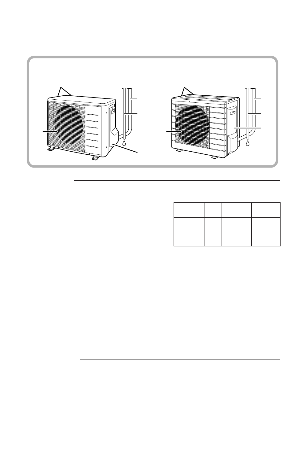
Outdoor Unit
15. Air inlet:
(Back and side)
16. Refrigerant piping and inter-unit cable
17. Drain hose
18. Earth terminal:
• It is inside of this cover.
19. Air outlet
Appearance of the outdoor unit may differ from some models.
25/35 class 50 class
16
17
18
19
15
16
17
18
19
15
Model
Mode
Temperature
setting
Air flow
rate
COOLING
ONLY
COOL
22˚C AUTO
HEAT
PUMP
AUTO
25˚C
AUTO