
Specifications
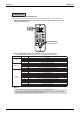
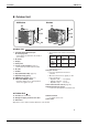
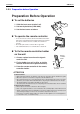
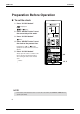
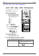
Table Of Contents
- Cover
- Table of Contents
- Part 1 List of Functions
- Part 2 Specifications
- Part 3 Printed Circuit Board Connector Wiring Diagram
- Part 4 Function and Control
- Part 5 Operation Manual
- Part 6 Service Diagnosis
- 1. Caution for Diagnosis
- 2. Problem Symptoms and Measures
- 3. Service Check Function
- 4. Code Indication on the Remote Controller
- 5. Troubleshooting
- 5.1 Indoor Units
- 5.2 Outdoor Units
- 5.3 Indoor Unit PCB Abnormality A1
- 5.4 Freeze-up Protection Control or High Pressure Control A5
- 5.5 Fan Motor or Related Abnormality A6
- 5.6 Thermistor or Related Abnormality (Indoor Unit) C4,C9
- 5.7 Front Panel Open / Close Fault C7
- 5.8 Signal Transmission Error (between Indoor and OutdoorUnit) U4
- 5.9 Unspecified Voltage (between Indoor and Outdoor Units) UA
- 5.10 Freeze-up Protection Control A5
- 5.11 Outdoor Unit PCB Abnormality E1
- 5.12 OL Activation (Compressor Overload) E5
- 5.13 Compressor Lock E6
- 5.14 DC Fan Lock E7
- 5.15 Input Over Current Detection E8
- 5.16 Discharge Pipe Temperature Control F3
- 5.17 High Pressure Control in Cooling F6
- 5.18 Compressor Sensor System Abnormality H0
- 5.19 Position Sensor Abnormality H6
- 5.20 CT or Related Abnormality H8
- 5.21 Thermistor or Related Abnormality (Outdoor Unit) P4,J3,J6,J8,J9,H9
- 5.22 Electrical Box Temperature Rise L3
- 5.23 Radiation Fin Temperature Rise L4
- 5.24 Output Over Current Detection L5
- 5.25 Insufficient Gas U0
- 5.26 Low-voltage Detection or Over-voltage Detection U2
- 5.27 Signal Transmission Error (on Outdoor Unit PCB) U7
- 5.28 Anti-icing Function in Other Rooms / UnspecifiedVoltage (between Indoor and Outdoor Units) UA,UH
- 6. Check
- Part 7 Removal Procedure
- Part 8 Others
- Part 9 Appendix
- Index
- Drawings & Flow Charts
Instruction SiBE12-713
180 Operation Manual
FAULT DIAGNOSIS BY REMOTE CONTROLLER
In the ARC433 series, the temperature display sections on the main unit indicate corresponding codes.
1.
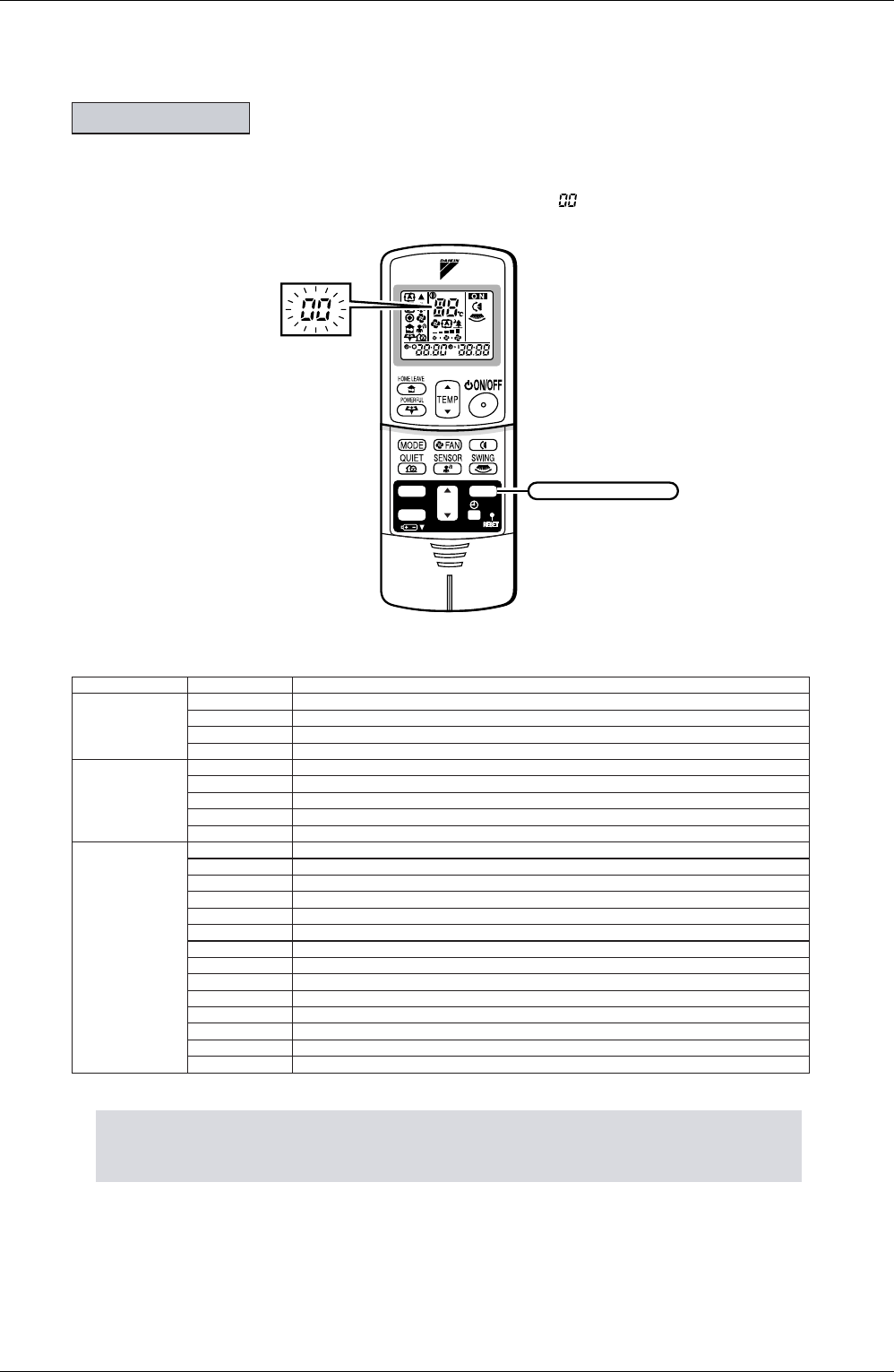
When the TIMER CANCEL button is held down for 5 seconds, a “ ” indication flashes on the
temperature display section.
2.
Press the TIMER CANCEL button repeatedly until a continuous beep is produced.
• The code indication changes as shown below, and notifies with a long beep.
NOTE
Fault diagnosis.
CODE MEANING
SYSTEM
00 NORMAL
U0 REFRIGERANT SHORTAGE
U2 DROP VOLTAGE OR MAIN CIRCUIT OVERVOLTAGE
U4 FAILURE OF TRANSMISSION (BETWEEN INDOOR UNIT AND OUTDOOR UNIT)
INDOOR UNIT
A1 INDOOR PCB DEFECTIVENESS
A5 HIGH PRESSURE CONTROL OR FREEZE-UP PROTECTOR
A6 FAN MOTOR FAULT
C4 FAULTY HEAT EXCHANGER TEMPERATURE SENSOR
C9 FAULTY SUCTION AIR TEMPERATURE SENSOR
OUTDOOR
UNIT
EA COOLING-HEATING SWITCHING ERROR
E5 OL STARTED
E6 FAULTY COMPRESSOR START UP
E7 DC FAN MOTOR FAULT
E8 OPERATION HALT DUE TO DETECTION OF INPUT OVER CURRENT
F3 HIGH TEMPERATURE DISCHARGE PIPE CONTROL
H6 OPERATION HALT DUE TO FAULTY POSITION DETECTION SENSOR
H8 CT ABNORMALITY
H9 FAULTY SUCTION AIR TEMPERATURE SENSOR
J3 FAULTY DISCHARGE PIPE TEMPERATURE SENSOR
J6 FAULTY HEAT EXCHANGER TEMPERATURE SENSOR
L4 HIGH TEMPERATURE AT INVERTER CIRCUIT HEATSINK
L5 OUTPUT OVERCURRENT
P4 FAULTY INVERTER CIRCUIT HEATSINK TEMPERATURE SENSOR
1.
A short beep and two consecutive beeps indicate non-corresponding codes.
2.
To cancel the code display, hold the TIMER CANCEL button down for 5 seconds. The code display
also cancel itself if the button is not pressed for 1 minute.
TIMER
ON
CANCEL
OFF
TIMER CANCEL button
It cancels the timer setting.