
Specifications
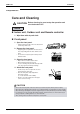
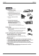
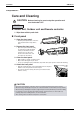
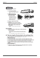
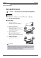
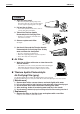
Table Of Contents
- Cover
- Table of Contents
- Part 1 List of Functions
- Part 2 Specifications
- Part 3 Printed Circuit Board Connector Wiring Diagram
- Part 4 Function and Control
- Part 5 Operation Manual
- Part 6 Service Diagnosis
- 1. Caution for Diagnosis
- 2. Problem Symptoms and Measures
- 3. Service Check Function
- 4. Code Indication on the Remote Controller
- 5. Troubleshooting
- 5.1 Indoor Units
- 5.2 Outdoor Units
- 5.3 Indoor Unit PCB Abnormality A1
- 5.4 Freeze-up Protection Control or High Pressure Control A5
- 5.5 Fan Motor or Related Abnormality A6
- 5.6 Thermistor or Related Abnormality (Indoor Unit) C4,C9
- 5.7 Front Panel Open / Close Fault C7
- 5.8 Signal Transmission Error (between Indoor and OutdoorUnit) U4
- 5.9 Unspecified Voltage (between Indoor and Outdoor Units) UA
- 5.10 Freeze-up Protection Control A5
- 5.11 Outdoor Unit PCB Abnormality E1
- 5.12 OL Activation (Compressor Overload) E5
- 5.13 Compressor Lock E6
- 5.14 DC Fan Lock E7
- 5.15 Input Over Current Detection E8
- 5.16 Discharge Pipe Temperature Control F3
- 5.17 High Pressure Control in Cooling F6
- 5.18 Compressor Sensor System Abnormality H0
- 5.19 Position Sensor Abnormality H6
- 5.20 CT or Related Abnormality H8
- 5.21 Thermistor or Related Abnormality (Outdoor Unit) P4,J3,J6,J8,J9,H9
- 5.22 Electrical Box Temperature Rise L3
- 5.23 Radiation Fin Temperature Rise L4
- 5.24 Output Over Current Detection L5
- 5.25 Insufficient Gas U0
- 5.26 Low-voltage Detection or Over-voltage Detection U2
- 5.27 Signal Transmission Error (on Outdoor Unit PCB) U7
- 5.28 Anti-icing Function in Other Rooms / UnspecifiedVoltage (between Indoor and Outdoor Units) UA,UH
- 6. Check
- Part 7 Removal Procedure
- Part 8 Others
- Part 9 Appendix
- Index
- Drawings & Flow Charts
Instruction SiBE12-713
168 Operation Manual
1. Open the front panel.
•
Open the front panel by placing a finger on the
panel tab on either side of the front panel and then
secure it using the supporting plate on the right.
2. Pull out the air filters.
• Push a little upwards the tab at the center of
each air f
ilter, then pull it down.
3.
Take off the Titanium Apatite
Photocatalytic Air-Purifying Filter.
• Hold the recessed parts of the frame and
unhook the four claws.
4. Clean or replace each filter.
See figure.
5. Set the air filter and the Titanium Apatite
Photocatalytic Air-Purifying Filter as they
were and close the front panel.
• Be sure to insert the two tabs below.
• Return the supporting plate to its previous position.
• Press either side of the front panel.
Air Filter
1. Wash the air filters with water or clean them with
vacuum cleaner.
•
If the dust does not come off easily, wash them with neutral detergent
thinned with lukewarm water, then dry them up in the shade.
• It is recommended to clean the air filters every two weeks.
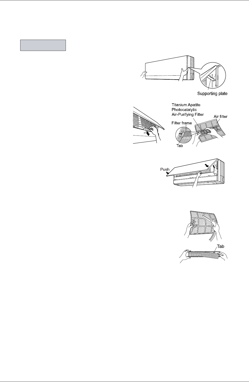
Titanium Apatite Photocatalytic
Air-Purifying Filter
(gray)
The Titanium Apatite Photocatalytic Air-Purifying Filter can be renewed
by washing it with water once every 6 months. We recommend replacing it o nce every 3 years.
[ Maintenance ]
1. Remove dust with a vacuum cleaner and wash lightly with water.
2.
If it is very dirty, soak it for 10 to 15 minutes in water mixed with a neutral cleaning agent.
3. Do not remove filter from frame when washing with water.
4. After washing, shake off remaining water and dry in the shade.
5.
Since the material is made out of paper, do not wring out the filter when removing water from it.
[ Replacement ]
1. Remove the tabs on the filter frame and replace with a new filter.
• Dispose of the old filter
as flammable waste.
Filters