
Specifications
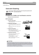
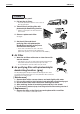
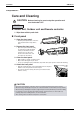
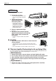
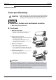
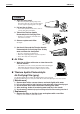
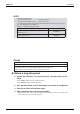
Table Of Contents
- Cover
- Table of Contents
- Part 1 List of Functions
- Part 2 Specifications
- Part 3 Printed Circuit Board Connector Wiring Diagram
- Part 4 Function and Control
- Part 5 Operation Manual
- Part 6 Service Diagnosis
- 1. Caution for Diagnosis
- 2. Problem Symptoms and Measures
- 3. Service Check Function
- 4. Code Indication on the Remote Controller
- 5. Troubleshooting
- 5.1 Indoor Units
- 5.2 Outdoor Units
- 5.3 Indoor Unit PCB Abnormality A1
- 5.4 Freeze-up Protection Control or High Pressure Control A5
- 5.5 Fan Motor or Related Abnormality A6
- 5.6 Thermistor or Related Abnormality (Indoor Unit) C4,C9
- 5.7 Front Panel Open / Close Fault C7
- 5.8 Signal Transmission Error (between Indoor and OutdoorUnit) U4
- 5.9 Unspecified Voltage (between Indoor and Outdoor Units) UA
- 5.10 Freeze-up Protection Control A5
- 5.11 Outdoor Unit PCB Abnormality E1
- 5.12 OL Activation (Compressor Overload) E5
- 5.13 Compressor Lock E6
- 5.14 DC Fan Lock E7
- 5.15 Input Over Current Detection E8
- 5.16 Discharge Pipe Temperature Control F3
- 5.17 High Pressure Control in Cooling F6
- 5.18 Compressor Sensor System Abnormality H0
- 5.19 Position Sensor Abnormality H6
- 5.20 CT or Related Abnormality H8
- 5.21 Thermistor or Related Abnormality (Outdoor Unit) P4,J3,J6,J8,J9,H9
- 5.22 Electrical Box Temperature Rise L3
- 5.23 Radiation Fin Temperature Rise L4
- 5.24 Output Over Current Detection L5
- 5.25 Insufficient Gas U0
- 5.26 Low-voltage Detection or Over-voltage Detection U2
- 5.27 Signal Transmission Error (on Outdoor Unit PCB) U7
- 5.28 Anti-icing Function in Other Rooms / UnspecifiedVoltage (between Indoor and Outdoor Units) UA,UH
- 6. Check
- Part 7 Removal Procedure
- Part 8 Others
- Part 9 Appendix
- Index
- Drawings & Flow Charts
SiBE12-713 Instruction
Operation Manual 167
FTXG 25/35 E, CTXG 50 E
Care and Cleaning
CAUTION
Indoor unit, Outdoor unit and Remote controller
1. Wipe them with dry soft cloth.
Front panel
1. Open the front panel.
• Open the front panel by placing a finger on the
panel tab on either side of the front panel.
2. Remove the front panel.
• With the front panel open so that it is almost hori-
zontal, slide it to the right.
The revolving axis on the left will come off.
The revolving axis on the right can be removed by
sliding the front panel to the left.
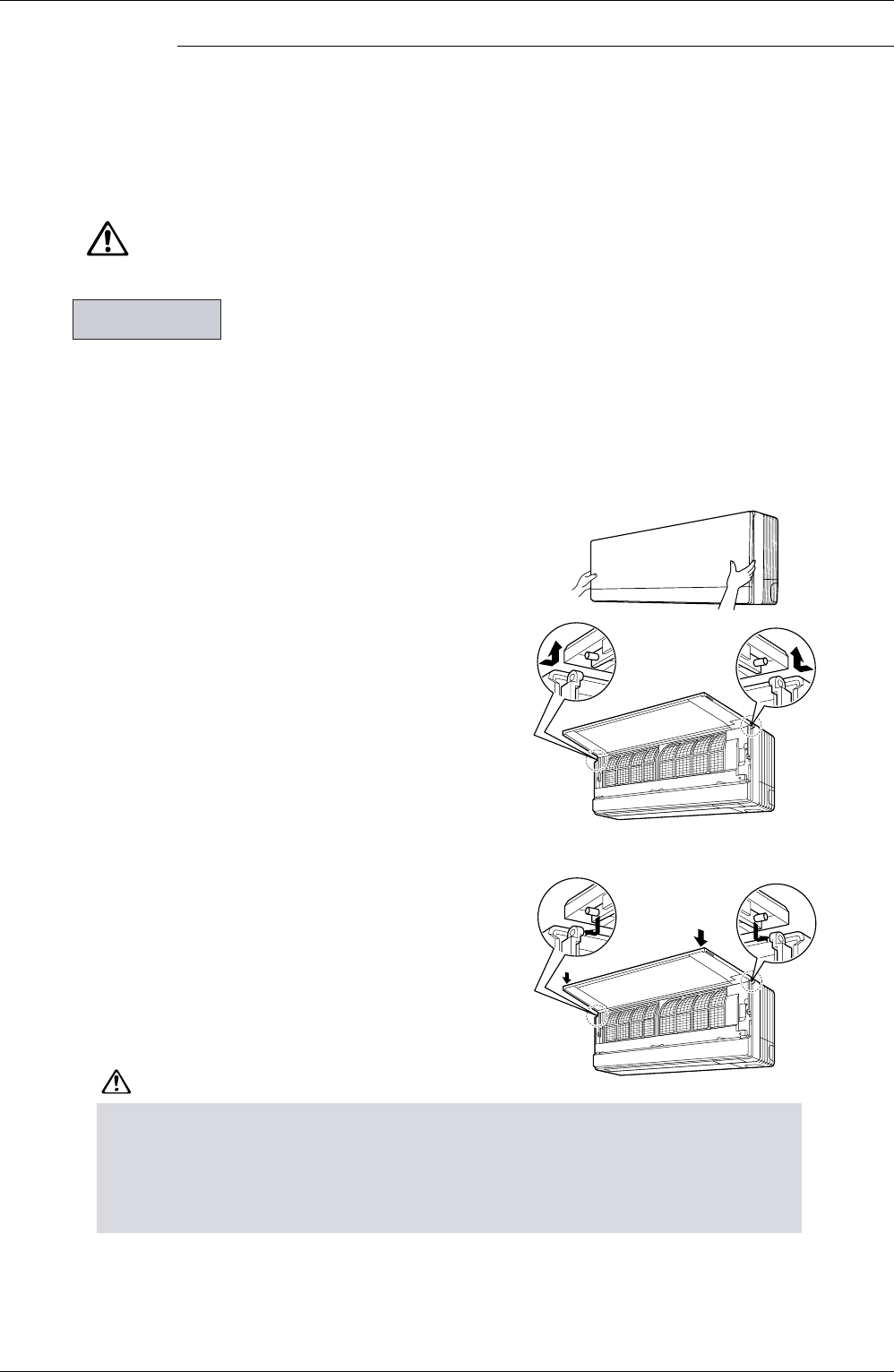
3. Clean the front panel.
• Wipe it with a soft cloth soaked in water.
• Only neutral detergent may be used.
• In case of washing the front panel with water, dry
it with cloth, dry it up
in the shade after washing.
4. Attach the front panel.
• Place the revolving axes on either side of the front
panel into the holes and slowly close.
(Press either side of the front panel.)
CAUTION
Units
•
Don’t touch the metal parts of the indoor unit. If you touch those parts, this may cause an injury.
•
When removing
or attaching the front panel, use a robust and stable stool and watch your steps carefully.
•
When removing or attaching the front panel, support the front panel securely with hand to prevent it from falling.
•
For cleaning, do not use hot water above 40
°
C, benzine, gasoline, thinner, nor other volatile oils, pol-
ishing compo
und, scrubbing brushes, nor other hand stuff.
•
After cleaning, make sure that the front panel is securely fixed.
•
Before cleaning, be sure to stop the operation and turn the breaker OFF.
•
Always shut down the unit (and close the panel) before doing any work.
Opening the panel during operation may cause the panel to fall off.