
Specifications
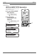
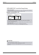
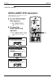
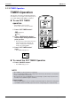
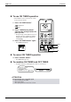
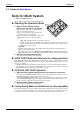
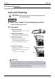
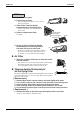
Table Of Contents
- Cover
- Table of Contents
- Part 1 List of Functions
- Part 2 Specifications
- Part 3 Printed Circuit Board Connector Wiring Diagram
- Part 4 Function and Control
- Part 5 Operation Manual
- Part 6 Service Diagnosis
- 1. Caution for Diagnosis
- 2. Problem Symptoms and Measures
- 3. Service Check Function
- 4. Code Indication on the Remote Controller
- 5. Troubleshooting
- 5.1 Indoor Units
- 5.2 Outdoor Units
- 5.3 Indoor Unit PCB Abnormality A1
- 5.4 Freeze-up Protection Control or High Pressure Control A5
- 5.5 Fan Motor or Related Abnormality A6
- 5.6 Thermistor or Related Abnormality (Indoor Unit) C4,C9
- 5.7 Front Panel Open / Close Fault C7
- 5.8 Signal Transmission Error (between Indoor and OutdoorUnit) U4
- 5.9 Unspecified Voltage (between Indoor and Outdoor Units) UA
- 5.10 Freeze-up Protection Control A5
- 5.11 Outdoor Unit PCB Abnormality E1
- 5.12 OL Activation (Compressor Overload) E5
- 5.13 Compressor Lock E6
- 5.14 DC Fan Lock E7
- 5.15 Input Over Current Detection E8
- 5.16 Discharge Pipe Temperature Control F3
- 5.17 High Pressure Control in Cooling F6
- 5.18 Compressor Sensor System Abnormality H0
- 5.19 Position Sensor Abnormality H6
- 5.20 CT or Related Abnormality H8
- 5.21 Thermistor or Related Abnormality (Outdoor Unit) P4,J3,J6,J8,J9,H9
- 5.22 Electrical Box Temperature Rise L3
- 5.23 Radiation Fin Temperature Rise L4
- 5.24 Output Over Current Detection L5
- 5.25 Insufficient Gas U0
- 5.26 Low-voltage Detection or Over-voltage Detection U2
- 5.27 Signal Transmission Error (on Outdoor Unit PCB) U7
- 5.28 Anti-icing Function in Other Rooms / UnspecifiedVoltage (between Indoor and Outdoor Units) UA,UH
- 6. Check
- Part 7 Removal Procedure
- Part 8 Others
- Part 9 Appendix
- Index
- Drawings & Flow Charts
Instruction SiBE12-713
158 Operation Manual
2.1.14 Care and Cleaning
FTK(X)S 20/25/35/50 D
Care and Cleaning
CAUTION
Indoor unit, Outdoor unit and Remote controller
1. Wipe them with dry soft cloth.
Front panel
1. Open the front panel.
•
Hold the panel by the tabs on the two sides and lift
it until it stops with a click.
2. Remove the front panel.
• Lift the front panel up, slide it slightly to the
right, and remove it from the horizontal axle
.
3. Clean the front panel.
•
Wipe it with a soft cloth soaked in water.
•
Only neutral detergent may be used.
•
In case of washing the panel with water, dry it with
cloth, dry it up in the shade after washing.
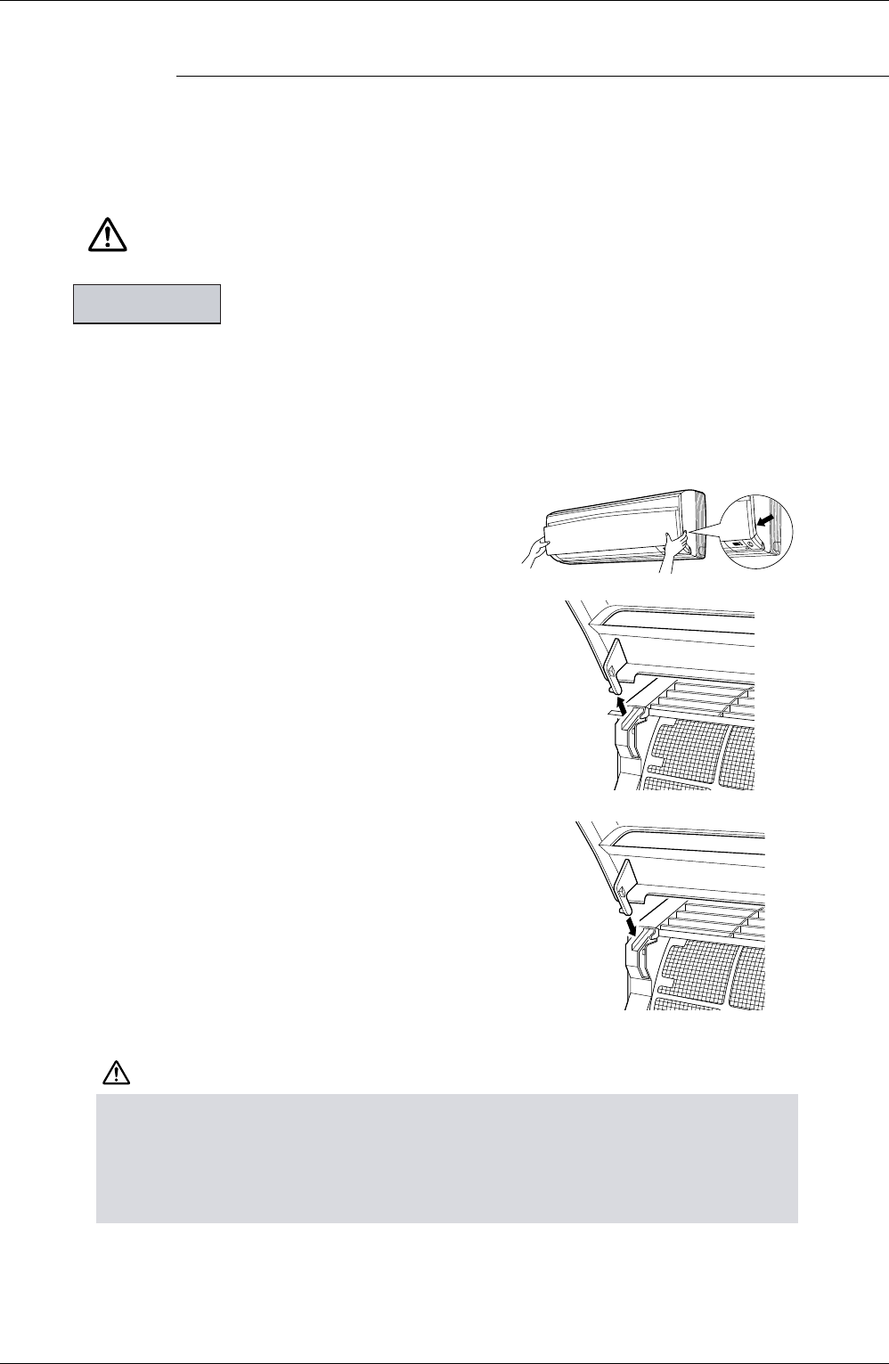
4. Attach the front panel.
•
Set the 2 keys of the front panel into the slots and
push them in all the way.
•
Close the front panel slowly and push the panel at
the 3 points.
(1 on each side and 1 in the middle.)
CAUTION
Units
•
Don’t touch the metal parts of the indoor unit. If you touch those parts, this may cause an injury.
•
When removing or attaching the front panel, use a robust and stable stool and watch your steps carefully.
•
When removing or attaching the front panel, support the panel securely with hand to prevent it from falling.
•
For cleaning, do not use hot water above 40
°
C, benzine, gasoline, thinner, nor other volatile oils, pol-
ishing compound, scrubbing brushes, nor other hand stuff.
•
After cleaning, make sure that the front panel is securely fixed.
Before cleaning, be sure to stop the operation and
turn the breaker OFF.
Fit the key
into the slot.