
Specifications
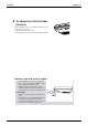
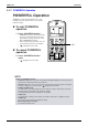
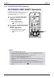
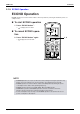

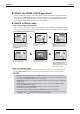
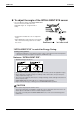
Table Of Contents
- Cover
- Table of Contents
- Part 1 List of Functions
- Part 2 Specifications
- Part 3 Printed Circuit Board Connector Wiring Diagram
- Part 4 Function and Control
- Part 5 Operation Manual
- Part 6 Service Diagnosis
- 1. Caution for Diagnosis
- 2. Problem Symptoms and Measures
- 3. Service Check Function
- 4. Code Indication on the Remote Controller
- 5. Troubleshooting
- 5.1 Indoor Units
- 5.2 Outdoor Units
- 5.3 Indoor Unit PCB Abnormality A1
- 5.4 Freeze-up Protection Control or High Pressure Control A5
- 5.5 Fan Motor or Related Abnormality A6
- 5.6 Thermistor or Related Abnormality (Indoor Unit) C4,C9
- 5.7 Front Panel Open / Close Fault C7
- 5.8 Signal Transmission Error (between Indoor and OutdoorUnit) U4
- 5.9 Unspecified Voltage (between Indoor and Outdoor Units) UA
- 5.10 Freeze-up Protection Control A5
- 5.11 Outdoor Unit PCB Abnormality E1
- 5.12 OL Activation (Compressor Overload) E5
- 5.13 Compressor Lock E6
- 5.14 DC Fan Lock E7
- 5.15 Input Over Current Detection E8
- 5.16 Discharge Pipe Temperature Control F3
- 5.17 High Pressure Control in Cooling F6
- 5.18 Compressor Sensor System Abnormality H0
- 5.19 Position Sensor Abnormality H6
- 5.20 CT or Related Abnormality H8
- 5.21 Thermistor or Related Abnormality (Outdoor Unit) P4,J3,J6,J8,J9,H9
- 5.22 Electrical Box Temperature Rise L3
- 5.23 Radiation Fin Temperature Rise L4
- 5.24 Output Over Current Detection L5
- 5.25 Insufficient Gas U0
- 5.26 Low-voltage Detection or Over-voltage Detection U2
- 5.27 Signal Transmission Error (on Outdoor Unit PCB) U7
- 5.28 Anti-icing Function in Other Rooms / UnspecifiedVoltage (between Indoor and Outdoor Units) UA,UH
- 6. Check
- Part 7 Removal Procedure
- Part 8 Others
- Part 9 Appendix
- Index
- Drawings & Flow Charts
SiBE12-713 Instruction
Operation Manual 141
2.1.7 POWERFUL Operation
POWERFUL Operation
POWERFUL operation quickly maximizes the cooling
(heating) effect in any operation mode. You can get the
maximum capacity.
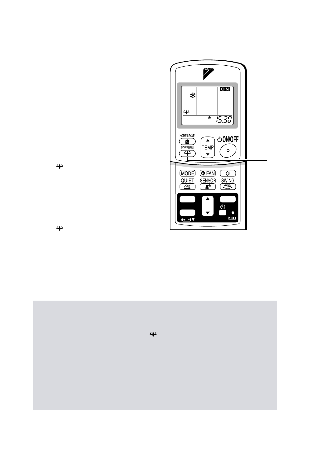
To start POWERFUL
operation
1. Press “POWERFUL button”.
• POWERFUL operation ends in 20 minutes.
Then the system automatically operates
again with the settings which were used
before POWERFUL operation.
• When using Powerful operation, there are
some functions which are not available.
• “ ” is displayed on the LCD.
To cancel POWERFUL
operation
2. Press “POWERFUL button”
again.
• “ ” disappears from the LCD.
NOTE
Notes on POWERFUL operation
• POWERFUL Operation cannot be used together with QUIET Operation. Priority is given to
the function of whichever button is pressed last.
•
POWERFUL Operation can only be set when the unit is running. Pressing the operation stop button
causes the settings to be canceled, and the “ ” disappears from the LCD.
•
In COOL and HEAT mode
To maximize the cooling (heating) effect, the capacity of outdoor unit must be increased
and the air flow rate be fixed to the maximum setting.
The temperature and air flow settings are not variable.
•
In DRY mode
The temperature setting is lowered by 2.5°C and the air flow rate is slightly increased.
•
In FAN mode
The air flow rate is fixed to the maximum setting.
TIMER
ON
CANCEL
OFF
1, 2
•
When using priority-room setting
See “Note for multi system”.