
Specifications
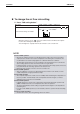
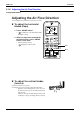
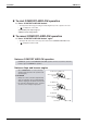
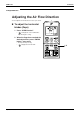
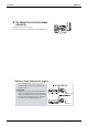
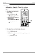
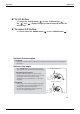
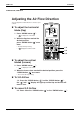
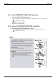
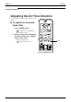
Table Of Contents
- Cover
- Table of Contents
- Part 1 List of Functions
- Part 2 Specifications
- Part 3 Printed Circuit Board Connector Wiring Diagram
- Part 4 Function and Control
- Part 5 Operation Manual
- Part 6 Service Diagnosis
- 1. Caution for Diagnosis
- 2. Problem Symptoms and Measures
- 3. Service Check Function
- 4. Code Indication on the Remote Controller
- 5. Troubleshooting
- 5.1 Indoor Units
- 5.2 Outdoor Units
- 5.3 Indoor Unit PCB Abnormality A1
- 5.4 Freeze-up Protection Control or High Pressure Control A5
- 5.5 Fan Motor or Related Abnormality A6
- 5.6 Thermistor or Related Abnormality (Indoor Unit) C4,C9
- 5.7 Front Panel Open / Close Fault C7
- 5.8 Signal Transmission Error (between Indoor and OutdoorUnit) U4
- 5.9 Unspecified Voltage (between Indoor and Outdoor Units) UA
- 5.10 Freeze-up Protection Control A5
- 5.11 Outdoor Unit PCB Abnormality E1
- 5.12 OL Activation (Compressor Overload) E5
- 5.13 Compressor Lock E6
- 5.14 DC Fan Lock E7
- 5.15 Input Over Current Detection E8
- 5.16 Discharge Pipe Temperature Control F3
- 5.17 High Pressure Control in Cooling F6
- 5.18 Compressor Sensor System Abnormality H0
- 5.19 Position Sensor Abnormality H6
- 5.20 CT or Related Abnormality H8
- 5.21 Thermistor or Related Abnormality (Outdoor Unit) P4,J3,J6,J8,J9,H9
- 5.22 Electrical Box Temperature Rise L3
- 5.23 Radiation Fin Temperature Rise L4
- 5.24 Output Over Current Detection L5
- 5.25 Insufficient Gas U0
- 5.26 Low-voltage Detection or Over-voltage Detection U2
- 5.27 Signal Transmission Error (on Outdoor Unit PCB) U7
- 5.28 Anti-icing Function in Other Rooms / UnspecifiedVoltage (between Indoor and Outdoor Units) UA,UH
- 6. Check
- Part 7 Removal Procedure
- Part 8 Others
- Part 9 Appendix
- Index
- Drawings & Flow Charts
Instruction SiBE12-713
138 Operation Manual
To start COMFORT AIRFLOW operation
5. Press “COMFORT AIRFLOW button”.
• The flap orientation will change, preventing air from blowing directly on the occupants of the
room.
• “ ” is displayed on the LCD.
〈COOL/DRY〉 The flap will go up.
〈HEAT〉 The flap will go down.
To cancel COMFORT AIRFLOW operation
6. Press “COMFORT AIRFLOW button” again.
• The flaps will return to the memory position from before COMFORT AIRFLOW mode.
• “ ” disappears from the LCD.
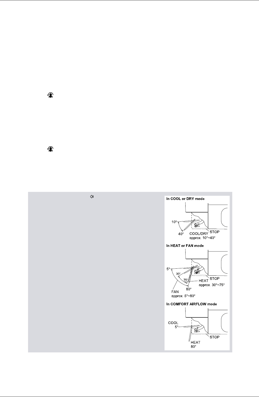
NOTE
• When
“SWING button ”
is selected, the flap swinging
range depends on the operation mode. (See the figure.)
Three-Dimensional (3-D) Airflow
• Using three-dimensional airflow circulates cold air, which
tends to collected at the bottom of the room, and hot air,
which tends to collect near the ceiling, throughout the
room, preventing
areas of cold and hot developing.
Comfort Airflow
• The air flow is set automatically
.
• The air direction is as shown in the figure at right.
ATTENTION
• Always use a remote controller to adjust the flap angle.
If you attempt to move it forcibly with hand when it is
swinging, the mechanism may be broken.
• Always use a remote controller to adjust the louvers
angles.