
Specifications
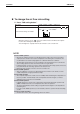
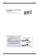
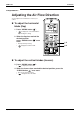
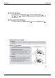
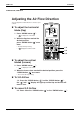
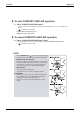
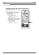
Table Of Contents
- Cover
- Table of Contents
- Part 1 List of Functions
- Part 2 Specifications
- Part 3 Printed Circuit Board Connector Wiring Diagram
- Part 4 Function and Control
- Part 5 Operation Manual
- Part 6 Service Diagnosis
- 1. Caution for Diagnosis
- 2. Problem Symptoms and Measures
- 3. Service Check Function
- 4. Code Indication on the Remote Controller
- 5. Troubleshooting
- 5.1 Indoor Units
- 5.2 Outdoor Units
- 5.3 Indoor Unit PCB Abnormality A1
- 5.4 Freeze-up Protection Control or High Pressure Control A5
- 5.5 Fan Motor or Related Abnormality A6
- 5.6 Thermistor or Related Abnormality (Indoor Unit) C4,C9
- 5.7 Front Panel Open / Close Fault C7
- 5.8 Signal Transmission Error (between Indoor and OutdoorUnit) U4
- 5.9 Unspecified Voltage (between Indoor and Outdoor Units) UA
- 5.10 Freeze-up Protection Control A5
- 5.11 Outdoor Unit PCB Abnormality E1
- 5.12 OL Activation (Compressor Overload) E5
- 5.13 Compressor Lock E6
- 5.14 DC Fan Lock E7
- 5.15 Input Over Current Detection E8
- 5.16 Discharge Pipe Temperature Control F3
- 5.17 High Pressure Control in Cooling F6
- 5.18 Compressor Sensor System Abnormality H0
- 5.19 Position Sensor Abnormality H6
- 5.20 CT or Related Abnormality H8
- 5.21 Thermistor or Related Abnormality (Outdoor Unit) P4,J3,J6,J8,J9,H9
- 5.22 Electrical Box Temperature Rise L3
- 5.23 Radiation Fin Temperature Rise L4
- 5.24 Output Over Current Detection L5
- 5.25 Insufficient Gas U0
- 5.26 Low-voltage Detection or Over-voltage Detection U2
- 5.27 Signal Transmission Error (on Outdoor Unit PCB) U7
- 5.28 Anti-icing Function in Other Rooms / UnspecifiedVoltage (between Indoor and Outdoor Units) UA,UH
- 6. Check
- Part 7 Removal Procedure
- Part 8 Others
- Part 9 Appendix
- Index
- Drawings & Flow Charts

Instruction SiBE12-713
130 Operation Manual
To change the air flow rate setting
5. Press “FAN setting button”.
• Indoor unit quiet operation
When the air flow is set to “ ”, the noise from the indoor unit will become quieter.
Use this when making the noise quieter.
The unit might lose capacity when the air flow rate is set to a weak level.
NOTE
DRY mode AUTO or HEAT or COOL or FAN mode
The air flow rate setting is not variable.
Five levels of air flow rate setting from “ ” to “ ”
plus “ ” “ ” are available.
Note on HEAT operation
•
Since this air conditioner heats the room by taking heat from outdoor air to indoors, the heating
capacity becomes smaller in lower outdoor temperatures. If the heating effect is insufficient, it is
recommended to use another heating appliance in combination with the air conditioner.
•
The heat pump system heats the room by circulating hot air around all parts of the room. After the
start of heating operation, it takes some time before the room gets warmer.
•
In heating operation, frost may occur on the outdoor unit and lower the heating capacity. In that case,
the system switches into defrosting operation to take away the frost.
•
During defrosting operation, hot air does not flow out of indoor unit.
Note on COOL operation
• This air conditioner cools the room by blowing the hot air in the room outside, so if the
outside temperature is high, performance drops.
Note on DRY operation
• The computer chip works to rid the room of humidity while maintaining the temperature as
much as possible. It automatically controls temperature and fan strength, so manual
adjustment of these functions is unavailable.
Note on AUTO operation
•
In AUTO operation, the system selects a temperature setting and an appropriate operation mode
(COOL or HEAT) based on the room temperature at the start of the operation.
•
The system automatically reselects setting at a regular interval to bring the room temperature to
user-setting level.
•
If you do not like AUTO operation, you can manually select the operation mode and setting
you like.
Note on air flow rate setting
•
At smaller air flow rates, the cooling (heating) effect is also smaller.