
Specifications
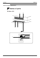
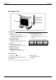
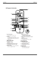
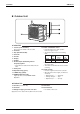
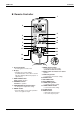
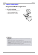
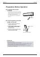
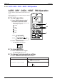
Table Of Contents
- Cover
- Table of Contents
- Part 1 List of Functions
- Part 2 Specifications
- Part 3 Printed Circuit Board Connector Wiring Diagram
- Part 4 Function and Control
- Part 5 Operation Manual
- Part 6 Service Diagnosis
- 1. Caution for Diagnosis
- 2. Problem Symptoms and Measures
- 3. Service Check Function
- 4. Code Indication on the Remote Controller
- 5. Troubleshooting
- 5.1 Indoor Units
- 5.2 Outdoor Units
- 5.3 Indoor Unit PCB Abnormality A1
- 5.4 Freeze-up Protection Control or High Pressure Control A5
- 5.5 Fan Motor or Related Abnormality A6
- 5.6 Thermistor or Related Abnormality (Indoor Unit) C4,C9
- 5.7 Front Panel Open / Close Fault C7
- 5.8 Signal Transmission Error (between Indoor and OutdoorUnit) U4
- 5.9 Unspecified Voltage (between Indoor and Outdoor Units) UA
- 5.10 Freeze-up Protection Control A5
- 5.11 Outdoor Unit PCB Abnormality E1
- 5.12 OL Activation (Compressor Overload) E5
- 5.13 Compressor Lock E6
- 5.14 DC Fan Lock E7
- 5.15 Input Over Current Detection E8
- 5.16 Discharge Pipe Temperature Control F3
- 5.17 High Pressure Control in Cooling F6
- 5.18 Compressor Sensor System Abnormality H0
- 5.19 Position Sensor Abnormality H6
- 5.20 CT or Related Abnormality H8
- 5.21 Thermistor or Related Abnormality (Outdoor Unit) P4,J3,J6,J8,J9,H9
- 5.22 Electrical Box Temperature Rise L3
- 5.23 Radiation Fin Temperature Rise L4
- 5.24 Output Over Current Detection L5
- 5.25 Insufficient Gas U0
- 5.26 Low-voltage Detection or Over-voltage Detection U2
- 5.27 Signal Transmission Error (on Outdoor Unit PCB) U7
- 5.28 Anti-icing Function in Other Rooms / UnspecifiedVoltage (between Indoor and Outdoor Units) UA,UH
- 6. Check
- Part 7 Removal Procedure
- Part 8 Others
- Part 9 Appendix
- Index
- Drawings & Flow Charts
Instruction SiBE12-713
128 Operation Manual
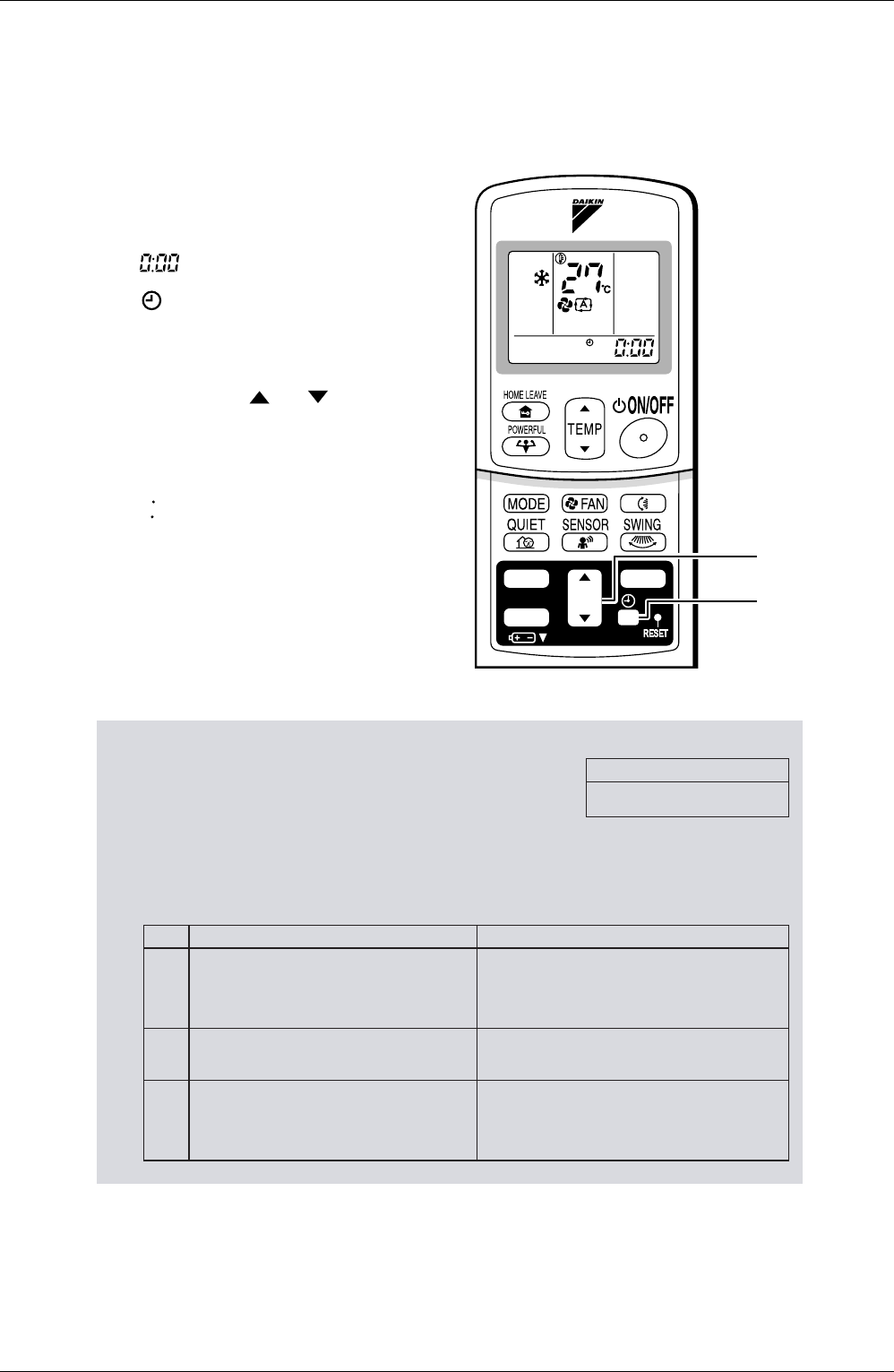
To set the clock
1. Press “CLOCK button”.
is displayed.
blinks.
2.
Press “TIMER setting button” to
set the clock to the present time.
Holding down “ ” or “ ” button
rapidly increases or decreases the time
display.
3. Press “CLOCK button”.
blinks.
Turn the breaker ON
•
Turning ON the breaker opens the flap, then
closes it again. (This is a normal procedure.)
NOTE
Tips for saving energy
•
Be careful not to cool (heat) the room too much.
Keeping the temperature setting at a moderate level helps save energy.
•
Cover windows with a blind or a curtain.
Blocking sunlight and air from outdoors increases the cooling (heating) effect.
•
Clogged air filters cause inefficient operation and waste energy. Clean them
once in about every two weeks.
Please note
•
The air conditioner always consumes 15-35 watts of electricity even while it is not operating.
•
If you are not going to use the air conditioner for a long period, for example in spring or autumn, turn the breaker OFF.
•
Use the air conditioner in the following conditions.
•
Operation outside this humidity or temperature range may cause a safety device to disable the system .
TIMER
ON
CANCEL
OFF
1, 3
2
Recommended temperature setting
For cooling:26
°
C – 28
°
C
For heating:20
°
C – 24
°
C
Mode Operating conditions If operation is continued out of this range
COOL
Outdoor temperature:〈2/3/MXS〉 –10 to 46°C
〈4/5MK(X)S〉 –10 to 46°C
〈RK(X)S〉 –10 to 46°C
Indoor temperature: 18 to 32°C
Indoor humidity: 80% max.
•
A safety device may work to stop the operation.
(In multi system, it may work to stop the operation of the
outdoor unit only.)
•
Condensation may occur on the indoor unit and drip.
HEAT
Outdoor temperature:〈2/3/4/5MXS〉 –15 to 15.5°C
〈RXS〉 –15 to 18°C
Indoor temperature: 10 to 30°C
•
A safety device may work to stop the operation.
DRY
Outdoor temperature:〈2/3/MXS〉 –10 to 46°C
〈4/5MK(X)S〉 –10 to 46°C
〈RK(X)S〉 –10 to 46°C
Indoor temperature: 18 to 32°C
Indoor humidity: 80% max.
•
A safety device may work to stop the operation.
• Condensation may occur on the indoor unit and drip.